Arduino Duemilanove — Board Fiche
⚡ The essentials in 60 seconds
- mcu — Atmel ATmega168 or ATmega328/328P — 8-bit AVR RISC, single core, 16 MHz crystal (build.f_cpu=16000000L). Datasheets: ATmega48/88/168 (doc2545, docs.arduino.cc mirror), ATmega328P (docs.arduino.cc mirror).
- gpu — none.
- memory — Flash 16 KB (ATmega168) or 32 KB (ATmega328), 2 KB used by bootloader → sketch space 14,336 B (upload.maximum_size=14336) / 30,720 B (upload.maximum_size=30720); SRAM 1 KB / 2 KB (upload.maximum_data_size=1024/2048); EEPROM 512 B / 1 KB (official page, boards.txt).
- connectivity — none on-board (no WiFi/BT/Ethernet/radio) — the ATmega168/328 provide UART TTL (5 V) on pins 0 (RX) / 1 (TX), plus I2C (TWI) and SPI; USB-to-TTL is handled by a separate chip (below). Radios/networking came from shields.
- usb — board-side FTDI FT232RL USB-to-TTL serial chip channels the UART over USB as a virtual COM port (FTDI VCP drivers); RX/TX LEDs flash on USB traffic (official page, "Communication"). FT232R family product page: ftdichip.com/products/ft232r/ (site blocks bot HEAD requests as of 2026-10-13 — HTTP 403; URL is the canonical FTDI page).
- gpio — (official page, "Input and Output"): - 14 digital I/O pins, 5 V logic, 40 mA per pin, internal pull-ups 20–50 kΩ. - PWM (8-bit, analogWrite): 3, 5, 6, 9, 10, 11. - External interrupts: 2 and 3 (attachInterrupt). - Serial: 0 (RX), 1 (TX) — TTL, tied to the FTDI chip. - SPI: 10 (SS), 11 (MOSI), 12 (MISO), 13 (SCK) (SPI library). - LED: 13 — on-board LED, HIGH = on. - 6 analog inputs, 10-bit resolution (0–1023), default 0–5 V range, updatable via AREF + analogReference. - I2C: A4 (SDA), A5 (SCL) (Wire library). - Reset pin (bring LOW) and AREF on the headers. - Pin-to-port mapping: official ATmega168 pin mapping.
- On this board : 9 tutorials · 10 code
The Arduino Duemilanove stands as a pivotal chapter in the history of open-source electronics, representing the bridge between the early experimental days of the Arduino project and the standardized, robust platform that millions of hobbyists and engineers would come to know. Released in 2009, a year that its Italian name literally translates to as "two thousand nine," this board was positioned as the latest iteration in a series of USB-enabled development boards. It served as the enhanced successor to the popular Diecimila model, refining the hardware design while introducing critical features that would define the Arduino ecosystem for years to come. Although it is now officially retired and no longer sold by Arduino, the Duemilanove remains a significant piece of hardware for understanding the evolution of microcontroller development. It was eventually superseded in the product lineup by the Arduino Uno in 2010, which marked a shift in how the board handled USB communication, but the Duemilanove remains a beloved classic among those who value its specific hardware architecture and historical significance.
At the heart of the Duemilanove lies the Atmel ATmega microcontroller, specifically the 8-bit AVR RISC architecture. Depending on the specific variant purchased, the board was shipped with either the ATmega168 or the ATmega328, with later production runs featuring the ATmega328P. This distinction is crucial for users today, as the two chips differ significantly in memory capacity and programming requirements. The ATmega168 offers 16 KB of flash memory, while the ATmega328 doubles this to 32 KB. However, in both cases, 2 KB of this flash space is reserved for the bootloader, a small program that allows the board to receive new code via USB without needing specialized hardware programmers. This leaves approximately 14,336 bytes of space for user sketches on the 168 model and 30,720 bytes on the 328 model. The board operates at a clock speed of 16 MHz, driven by a crystal oscillator, which dictates how fast the processor can execute instructions. For those new to electronics, think of this frequency as the heartbeat of the computer; a higher frequency generally means more operations per second, though in this case, 16 MHz was more than sufficient for the real-time control tasks the board was designed to handle.
One of the most defining characteristics of the Duemilanove, and a key reason for its historical importance, is its method of connecting to a computer. Unlike modern Arduino boards that use a dedicated microcontroller chip to handle USB communication, the Duemilanove relies on a separate FTDI FT232RL chip. This component acts as a bridge, converting the serial signals from the main microcontroller into USB signals that a computer can understand, and vice versa. This setup creates a virtual COM port on the user’s computer, allowing for easy programming and data monitoring. A practical consequence of this architecture is that the board’s 3.3-volt power rail is generated by this FTDI chip, which limits the current available on that pin to a modest 50 milliamps. This means that while the 3.3V pin is useful for powering small sensors or logic-level shifting, it cannot support heavier loads, which would require an external voltage regulator. Additionally, because the USB connection is handled by a dedicated chip rather than the main processor, the serial communication behaves differently during resets compared to newer boards, a nuance that developers must keep in mind when writing software that communicates with the host computer.
The input and output capabilities of the Duemilanove established the physical layout that became the standard for Arduino shields, the add-on modules that plug directly into the board. It features 14 digital input/output pins, six of which can generate Pulse Width Modulation (PWM) signals. PWM is a technique used to simulate analog output by rapidly switching a digital pin on and off, allowing for control over things like motor speed or LED brightness. The board also includes six analog input pins, which can read continuous voltage levels from sensors, converting them into digital values with a 10-bit resolution. This means the board can distinguish between 1,024 different voltage levels within its 0 to 5-volt range. These pins are arranged in a specific grid pattern, though it is worth noting a subtle physical quirk: the distance between digital pins 7 and 8 is 160 mils, whereas the standard spacing for the other pins is 100 mils. This irregularity was a legacy design choice that shield manufacturers had to account for, but it remains a recognizable feature of the classic Arduino form factor.
Power management on the Duemilanove was a significant improvement over its predecessors. The board introduced automatic power selection, meaning it could seamlessly switch between power supplied via the USB cable and an external power source, such as a battery or wall adapter, without user intervention. This was a major convenience for projects that needed to run independently of a computer. The external power is supplied through a 2.1 mm center-positive barrel jack, with a recommended voltage range of 7 to 12 volts. The onboard linear regulator steps this voltage down to a stable 5 volts for the microcontroller and other components. Users must be cautious with this input; supplying less than 7 volts can result in an unstable 5-volt rail, while voltages above 12 volts can cause the regulator to overheat, potentially damaging the board. Furthermore, the USB connection is protected by a resettable polyfuse that will break the circuit if the current draw exceeds 500 milliamps, protecting the computer’s USB port from damage.
Programming the Duemilanove is done using the Arduino Integrated Development Environment (IDE) or command-line tools, utilizing the same C/C++ based language that Arduino is famous for. However, because the board shares its core definition with the Diecimila, users must carefully select the correct board type and processor in the software settings. Choosing the wrong option, such as selecting the ATmega168 profile for an ATmega328 chip, will result in failed uploads because the bootloader communication speeds differ: 19,200 baud for the 168 and 57,600 baud for the 328. The upload process itself involves a brief reset of the board, triggered by a signal from the FTDI chip, which activates the bootloader for about half a second. During this window, the first bytes of data sent from the computer are often ignored, so software that communicates immediately upon connection needs to include a short delay to ensure reliable communication.
Despite its retirement, the Duemilanove remains a fully functional and open-hardware platform. The full schematic and reference design are publicly available, allowing enthusiasts to repair, modify, or even manufacture their own versions. It serves as an excellent entry point for learning embedded systems, offering a tangible connection to the roots of the Arduino movement. While it lacks the built-in WiFi or Bluetooth connectivity of modern boards, its simplicity and robustness make it ideal for learning the fundamentals of digital and analog electronics. Whether you are blinking an LED, reading a sensor, or controlling a motor, the Duemilanove provides a stable and well-documented foundation. Its legacy lives on not just in the boards that replaced it, but in the vast community of makers who learned their craft on this very hardware, proving that even retired technology can continue to educate and inspire.
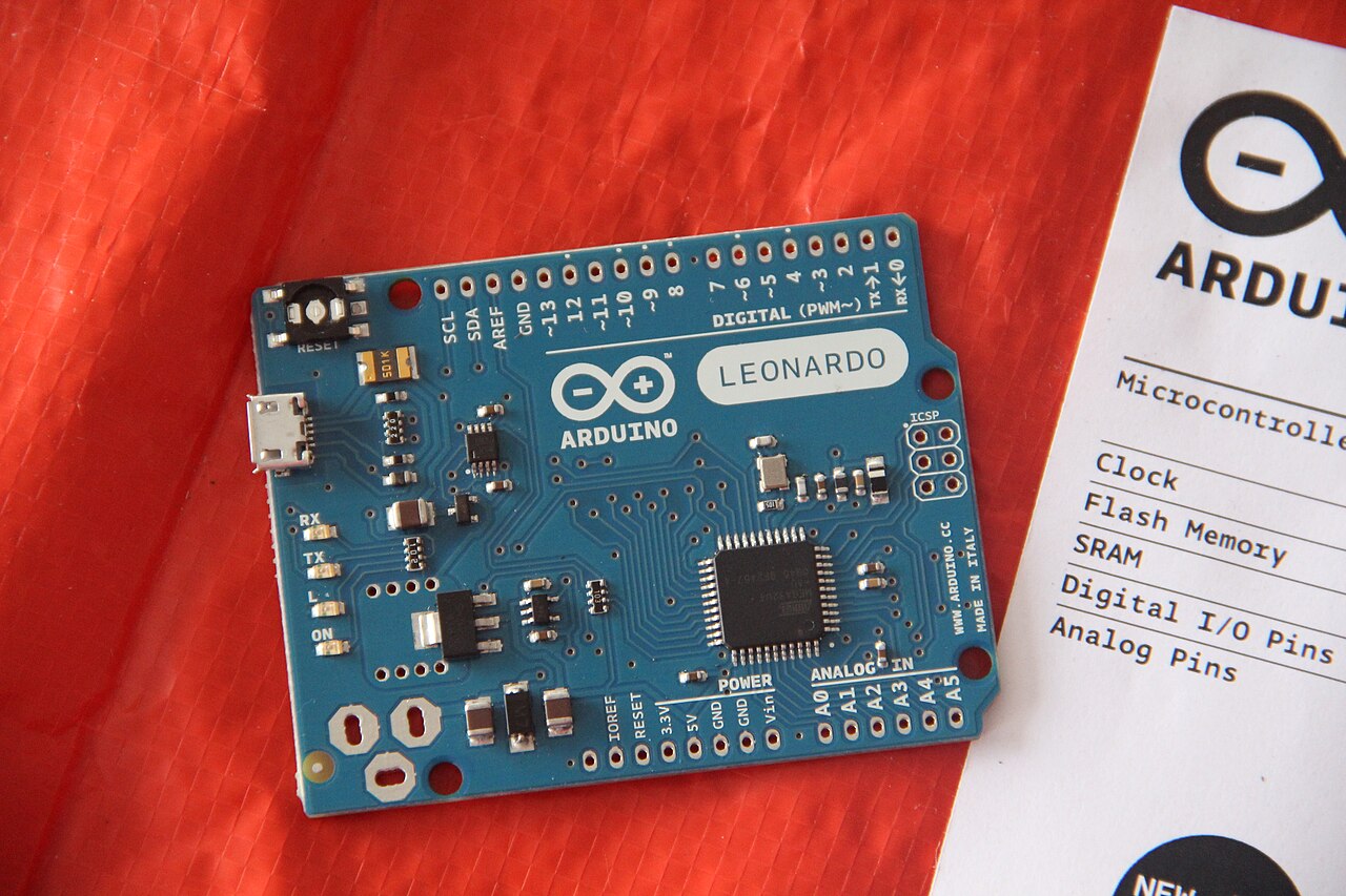
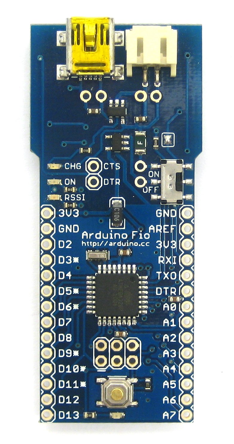
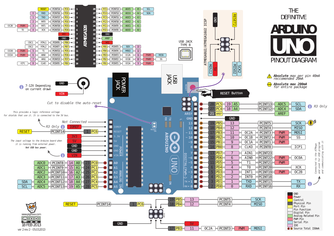
Pinout diagram
| Attr | Specs | verified |
|---|---|---|
mcu | Atmel ATmega168 or ATmega328/328P — 8-bit AVR RISC, single core, 16 MHz crystal (build.f_cpu=16000000L). Datasheets: ATmega48/88/168 (doc2545, docs.arduino.cc mirror), ATmega328P (docs.arduino.cc mirror). | ✔ |
gpu | none. | ? unverified |
memory | Flash 16 KB (ATmega168) or 32 KB (ATmega328), 2 KB used by bootloader → sketch space 14,336 B (upload.maximum_size=14336) / 30,720 B (upload.maximum_size=30720); SRAM 1 KB / 2 KB (upload.maximum_data_size=1024/2048); EEPROM 512 B / 1 KB (official page, boards.txt). | ✔ |
connectivity | none on-board (no WiFi/BT/Ethernet/radio) — the ATmega168/328 provide UART TTL (5 V) on pins 0 (RX) / 1 (TX), plus I2C (TWI) and SPI; USB-to-TTL is handled by a separate chip (below). Radios/networking came from shields. | ? unverified |
usb | board-side FTDI FT232RL USB-to-TTL serial chip channels the UART over USB as a virtual COM port (FTDI VCP drivers); RX/TX LEDs flash on USB traffic (official page, "Communication"). FT232R family product page: ftdichip.com/products/ft232r/ (site blocks bot HEAD requests as of 2026-10-13 — HTTP 403; URL is the canonical FTDI page). | ✔ |
gpio | (official page, "Input and Output"): - 14 digital I/O pins, 5 V logic, 40 mA per pin, internal pull-ups 20–50 kΩ. - PWM (8-bit, analogWrite): 3, 5, 6, 9, 10, 11. - External interrupts: 2 and 3 (attachInterrupt). - Serial: 0 (RX), 1 (TX) — TTL, tied to the FTDI chip. - SPI: 10 (SS), 11 (MOSI), 12 (MISO), 13 (SCK) (SPI library). - LED: 13 — on-board LED, HIGH = on. - 6 analog inputs, 10-bit resolution (0–1023), default 0–5 V range, updatable via AREF + analogReference. - I2C: A4 (SDA), A5 (SCL) (Wire library). - Reset pin (bring LOW) and AREF on the headers. - Pin-to-port mapping: official ATmega168 pin mapping. | ✔ |
power | (official page, "Power"): - Powered from USB or external supply, selected automatically ("automatic power selection" was a Duemilanove addition over the Diecimila — archived store description, Wayback 2011-11-01). - External: 2.1 mm center-positive barrel jack, or battery into Gnd/Vin of the POWER header. Recommended 7–12 V, limits 6–20 V; <7 V makes the 5 V rail unstable, >12 V can overheat the regulator. - Pins: VIN (raw external input), 5V (regulated), 3V3 — generated by the on-board FTDI chip, max 50 mA, GND. - USB overcurrent protection: resettable polyfuse, breaks the USB link above 500 mA (official page). | ✔ |
mechanicals | max PCB size 2.7 × 2.1 in (USB connector and power jack overhang), three screw holes; note the distance between digital pins 7 and 8 is 160 mil, not the 100 mil grid (official page, "Physical Characteristics"). | ✔ |
- Manufacturer: Arduino S.r.l. (Italy). Official (retired) product page: docs.arduino.cc/retired/boards/arduino-duemilanove/, markdown source content.md in arduino/docs-content.
- Product: The Arduino Duemilanove ("2009" in Italian, named after the year of its release) is a microcontroller board based on the ATmega168 or ATmega328, with 14 digital I/O (6 PWM), 6 analog inputs, a 16 MHz crystal, USB, power jack, ICSP header and reset button — "the latest in a series of USB Arduino boards" at the time, and the enhanced successor of the Diecimila (official retired page).
- Year: 2009 (the name literally means "two thousand nine" in Italian; official page: "named after the year of its release").
- Launch price:
- Status: End-of-life / retired. The board lives under the "retired" section of Arduino's docs (retired boards page), and returns 404 as of 2026-10-13 (verified by direct request). It was superseded in the lineup by the Arduino Uno (2010), which replaced the FTDI USB-serial chip with an ATmega16U2 (Uno rev3 tech-specs.yml in docs-content: "USB-Serial Processor: ATmega16U2 16 MHz").
- SKU / variants: SKU A000001 = "Arduino Duemilanove w/ Atmega328" (title of the archived official store product page, snapshot 2011-11-01, Wayback Machine). Two MCU variants were sold: ATmega168 and ATmega328; later boards shipped with the ATmega328P (store description 2011: "new processor ATMega328P re-loaded with bootloader"; the current core builds atmega328p, boards.txt).
+ Strengths
- The 2009 flagship — first 328-class Arduino: the Duemilanove was the first board in the mainline USB series to offer the ATmega328 (double the flash/SRAM of the ATmega168), sold as "the new processor ATMega328P" on the official store (archived store page, 2011-11-01).
- Diecimila refinements consolidated: auto-reset via DTR, extended power connector, built-in LED on 13, USB overcurrent polyfuse and automatic USB/external power selection — all listed as its differentiators in the official store description (archived store page, official page).
- FTDI FT232RL USB serial — the last mainline Arduino family to use a real FTDI bridge; the successor Uno (2010) moved USB to an ATmega16U2 (Uno rev3 tech-specs.yml). Practical difference: on the Duemilanove the 3.3 V rail is powered by the FTDI chip (50 mA max) and the serial port survives MCU resets differently (DTR-based, not CDC-enumeration-based) (official page).
- Classic shield-format GPIO set: 14 D (6 PWM) + 6 A (10-bit) + I2C + SPI + UART at 5 V, 40 mA/pin — the pinout that became the Arduino shield standard (official page).
- Open hardware: full EAGLE reference design and schematic published and still live: schematic PDF, reference design ZIP (both verified 200 OK on 2026-10-13).
- Bootloader source in-tree: the exact ATmegaBOOT sources and per-board HEX files ship with ArduinoCore-avr, so the bootloader can be rebuilt/flashed from source (bootloaders/atmega/).
− Weaknesses
- Two CPUs, one board name: you must pick the board entry matching the actual chip ("according to the microcontroller on your board" — official Programming section). A sketch compiled/flashed for the wrong CPU fails because upload speed and flash size differ: 19200 baud / 14,336 B (168) vs 57600 baud / 30,720 B (328) (official page, boards.txt).
- ~0.5 s bootloader window + swallowed first bytes: opening the port resets the board; the bootloader intercepts the first bytes for ~half a second. Host-side config protocols must wait ~1 s after opening the port (official page, "Automatic (Software) Reset").
- 3.3 V pin is weak and FTDI-fed: max 50 mA, generated by the FT232RL — heavier 3.3 V loads need their own regulator (official page, "Power").
- Regulator headroom traps: below 7 V on the jack the 5 V rail may sag; above 12 V the linear regulator can overheat and damage the board (official page, "Power").
- Polyfuse trip: >500 mA on USB opens the resettable fuse — the board appears "dead" until the fault clears and power cycles (official page, "USB Overcurrent Protection").
- Shield footprint gotcha: the gap between digital pins 7 and 8 is 160 mil, not 100 mil — headers/shields must account for it (official page, "Physical Characteristics").
- Stale spec in old marketing: the archived store page claims "0.5 KB used by bootloader" for the 328 version, contradicting the official board page ("2 KB used by bootloader") and boards.txt sketch sizes (32768 − 30720 = 2048 B). Trust 2 KB (store page 2011 vs official page / boards.txt).
- EOL support: not sold (store 404 verified 2026-10-13); docs frozen under retired/; Windows users may need to install the legacy FTDI VCP driver manually (official page).
- Counterfeit FTDI/driver saga: the Duemilanove clone market is flooded with counterfeit FT232R chips, and FTDI driver updates have historically bricked them on Windows.
- Old-bootloader millis overflow on pre-2009 boards: the NG/Diecimila-era ATmega168 bootloader had a timer0 overflow bug affecting millis after ~93 minutes, fixed in the 2009 bootloader used on Duemilanove.
- Retour d'expérience expert expert — expert-arduino
- Petit rappel pour les nouveaux arrivants sur cette carte mythique mais retiree du catalogue. La Duemilanove est souvent mal comprise a cause de ses deux variantes de microcontroleur. Si vous avez une ATmega168, selectionnez bien l'entrée correspondante dans l'IDE, sinon le flashage échoue a cause d… — expert-arduino
- Merci pour le rappel. J'ai effectivement rencontre le problème de la pin 3.3V en essayant de connecter un petit module Bluetooth. La carte coupait tout des que j'activais le module. Je pensais a un defaut matériel, mais c'etait bien la limite des 50 mA depassee. Du coup, j'utilise maintenant un reg… — maker-furtif
- Ce n'est pas la puce FTDI, c'est le comportement normal du bootloader. Quand tu ouvres le port série, la carte se reset automatiquement. Le bootloader prend la main pendant environ 0,5 seconde pour vérifier s'il faut uploader un programme. Si ton script envoit des données immediatement, ces premier… — bricoleur-78
Community feedback and projects
- Duemilanove: Classic or Retro Update? forum.arduino.cc
- Duemilanove: Historical Artifact or Unicorn? forum.arduino.cc
- Port Code From Arduino Duemilanove to UNO R4 WIFI forum.arduino.cc
- ZIP del diseño de referencia EAGLE other
- PDF del esquema schematic
- ATmega328P (espejo Arduino) datasheet
- ATmega48/88/168 doc2545 (espejo Arduino) datasheet
- docs-content repo
- Retired official product page
- ArduinoCore-avr boards.txt
- ATmegaBOOT_168.c source
- prebuilt HEX files
- Bootloader wiki page (retired)
- schematic PDF
- EAGLE reference design ZIP
- ATmega48/88/168 doc2545 (Arduino mirror)
- ATmega328P (Arduino mirror)
- Microchip ATmega328P product page
- FTDI FT232R product page
- ATmega168 pin mapping (retired docs)
- Programmer tutorial (retired docs)
- ArduinoISP example
- Uno rev3 tech-specs.yml
- product page A000001, €15.00, 2011-11-01
- catalog listing €18.00, 2011-05-28
- Arduino forum
- Wikipedia: Arduino
- Two CPUs, one board name: you must pick the board entry matching the actual chip ("according to the microcontroller on your board" — official Programming section). A sketch compiled/flashed for the wrong CPU fails because upload speed and flash size differ: 19200 baud / 14,336 B (168) vs 57600 baud / 30,720 B (328) (official page, boards.txt).
- ~0.5 s bootloader window + swallowed first bytes: opening the port resets the board; the bootloader intercepts the first bytes for ~half a second. Host-side config protocols must wait ~1 s after opening the port (official page, "Automatic (Software) Reset").
- 3.3 V pin is weak and FTDI-fed: max 50 mA, generated by the FT232RL — heavier 3.3 V loads need their own regulator (official page, "Power").
- Regulator headroom traps: below 7 V on the jack the 5 V rail may sag; above 12 V the linear regulator can overheat and damage the board (official page, "Power").
- Polyfuse trip: >500 mA on USB opens the resettable fuse — the board appears "dead" until the fault clears and power cycles (official page, "USB Overcurrent Protection").
- Shield footprint gotcha: the gap between digital pins 7 and 8 is 160 mil, not 100 mil — headers/shields must account for it (official page, "Physical Characteristics").
- Stale spec in old marketing: the archived store page claims "0.5 KB used by bootloader" for the 328 version, contradicting the official board page ("2 KB used by bootloader") and boards.txt sketch sizes (32768 − 30720 = 2048 B). Trust 2 KB (store page 2011 vs official page / boards.txt).
- EOL support: not sold (store 404 verified 2026-10-13); docs frozen under retired/; Windows users may need to install the legacy FTDI VCP driver manually (official page).
- Counterfeit FTDI/driver saga: the Duemilanove clone market is flooded with counterfeit FT232R chips, and FTDI driver updates have historically bricked them on Windows.
- Old-bootloader millis overflow on pre-2009 boards: the NG/Diecimila-era ATmega168 bootloader had a timer0 overflow bug affecting millis after ~93 minutes, fixed in the 2009 bootloader used on Duemilanove.
- Faire clignoter la LED 13 d'une Duemilanove (et choisir le bon ATmega) debutant Schéma : IMG-duemilanove-debutant-1-clignoter-led-13-duemilanove.svg — Arduino Duemilanove vue de dessus, puce ATmega DIP-28 et puce FTDI FT232RL annotées, LED marquée L près de la broche 13 surlignée, câble mini-USB branché, sélecteur IDE « Duemilanove w/ ATmega328 » en encart.
- Bouton poussoir et moniteur série sur la Duemilanove (avec ses 0,5 s de silence) debutant Schéma : IMG-duemilanove-debutant-2-bouton-poussoir-serial-ftdi.svg — bouton poussoir entre la broche 2 et GND sur une Arduino Duemilanove, résistance interne pull-up annotée 20–50 kΩ, moniteur série affichant ETAT=1 / ETAT=0, puce FTDI et LED TX clignotante.
- Potentiomètre et variation LED : l'ADC 10 bits et le PWM 8 bits version AVR debutant Schéma : IMG-duemilanove-debutant-3-potentiometre-pwm-fade.svg — potentiomètre 10 kΩ câblé entre 5 V, A0 et GND sur une Arduino Duemilanove, LED + résistance 220 Ω sur la broche PWM 9, liste des broches PWM 3/5/6/9/10/11 surlignée, ADC 10 bits annoté.
- Ajouter un deuxième port série avec SoftwareSerial (GPS sur broches 10/11) intermediaire Schéma : IMG-duemilanove-intermediaire-1-gps-softwareserial.svg — module GPS TTL alimenté en 5 V relié à l'Arduino Duemilanove sur broches 10 (RX) et 11 (TX) en croix, puce FTDI occupant déjà les broches 0/1, mention « un seul UART matériel, occupé par l'USB ».
- Régler la référence de mesure avec AREF et analogReference intermediaire Schéma : IMG-duemilanove-intermediaire-2-reference-aref-mesure-precise.svg — Arduino Duemilanove avec potentiomètre alimenté en 3V3, broche AREF reliée au 3V3 via un interrupteur, fonction analogReference(EXTERNAL) annotée, comparaison de deux mesures 10 bits (réf 5 V vs réf 3,3 V).
- Persister une calibration dans l'EEPROM de l'ATmega (512 octets ou 1 Ko) intermediaire Schéma : IMG-duemilanove-intermediaire-3-eeprom-persister-calibration.svg — Arduino Duemilanove avec puce ATmega328 dont la zone EEPROM 1 Ko est surlignée, bouton sur broche 2 pour sauvegarder, moniteur série affichant la valeur rechargée après rebranchement de l'alimentation.
- Convertir la Duemilanove en programmateur AVR (ArduinoISP) pour graver des puces nues avance Schéma : IMG-duemilanove-avance-1-duemilanove-programmateur-avrisp.svg — Arduino Duemilanove reliée par son connecteur ICSP 2×3 à une ATmega328P sur plaque d'essai, six fils MOSI/MISO/SCK/VCC/GND/RESET étiquetés, IDE affichant le programmeur « Arduino as ISP », broche 10 en RESET du circuit cible annotée.
- Manipulation directe des registres PORT : le bit-banging à 16 MHz avance Schéma : IMG-duemilanove-avance-2-manipulation-registres-port-avr.svg — boîtier ATmega328 vu de dessus avec les ports PORTB (broches 8 à 13) et PORTD (broches 0 à 7) surlignés, tableau de correspondance broche Arduino → bit de port (broche 13 = PORTB bit 5), oscilloscope montrant un créneau rapide sur la broche 13.
- Resusciter une Duemilanove sans bootloader : ICSP, fusibles et ATmegaBOOT avance Schéma : IMG-duemilanove-avance-3-resusciter-bootloader-icsp-fuses.svg — Arduino Duemilanove avec la puce ATmega en plan éclaté, connecteur ICSP 2×3 relié à un programmateur USBtinyISP, terminal affichant des commandes avrdude de lecture des fusibles (low=0xFF, high=0xDA, extended=0xFD) et de réécriture du fichier ATmegaBOOT_168_atmega328.hex.
Code library — examples written for this board
clignotante.inoArduinobouton-led.inoArduinopwm-respiration.inoArduinopotentiometre-plotter.inoArduinoservo-balayage.inoArduinobuzzer-melodie.inoArduinoscanner-i2c.inoArduinoeeprom-log.inoArduinosommeil-batterie.inoArduinocommande-serie.inoArduino
Examples and repos found online
- arduino/ArduinoCore-avr github.com
- arduino/Arduino github.com
- arduino-libraries/LiquidCrystal github.com
- razerbeans/WebSocket-Arduino github.com
- alvieboy/arduino-oscope github.com