Arduino GIGA R1 WiFi
⚡ The essentials in 60 seconds
- soc — STMicroelectronics STM32H747XI, dual-core 32-bit Arm (store Tech Specs, st.com product page, both fetched 2026-10-13).
- cpu — Cortex-M7 @ up to 480 MHz + Cortex-M4 @ up to 240 MHz; FPU (single/double precision on M7, IEEE-754), full DSP instruction set, MPU (st.com).
- gpu — none — display-controller-class peripheral only; the display connector carries DPI signals (see below).
- memory — 2 MB dual-bank flash + 1 MB RAM (192 KB TCM, up to 864 KB user SRAM, 4 KB backup SRAM) (st.com; store lists "2MB Flash, 1MB RAM").
- wireless — Murata 1DX (LBEE5KL1DX-883) module — Wi-Fi 802.11b/g/n up to 65 Mbps + Bluetooth LE — with u.FL antenna supplied in the box; no on-board antenna (store Tech Specs + FAQ, docs hardware page).
- secure_element — ATECC608A-MAHDA-T cryptoauthentication chip (store Tech Specs).
- On this board : 9 tutorials · 10 code
The Arduino GIGA R1 WiFi stands as the flagship high-performance microcontroller board in the Arduino lineup, designed for ambitious makers who require more processing power and connectivity than traditional entry-level boards can provide. Announced at the end of 2023 and currently available for purchase under the SKU ABX00063, this board occupies the classic Mega and Due form factor, measuring 101 by 53 millimeters. This physical size is not merely aesthetic; it provides the necessary real estate to expose a vast array of input and output pins through standard 2.54-millimeter headers, making it significantly easier to prototype complex projects compared to high-density production boards like the Portenta H7, which shares similar internal architecture. The board is manufactured by Arduino S.r.l. in Monza, Italy, a company that has been owned by Qualcomm since October 2025, and it is marketed as a solution for those with "bigger ideas" who need robust hardware capabilities.
At the heart of the GIGA R1 WiFi lies the STMicroelectronics STM32H747XI, a dual-core 32-bit Arm microcontroller that defines the board’s performance ceiling. This system-on-chip features two distinct processing units: a Cortex-M7 core running at up to 480 MHz and a Cortex-M4 core running at up to 240 MHz. To explain this simply, the Cortex-M7 is the high-performance engine capable of handling complex calculations, while the Cortex-M4 acts as a co-processor that can handle background tasks or real-time operations independently. This true dual-core architecture allows developers to run different operating systems or applications on each core simultaneously, such as running MicroPython on one core and standard Arduino code on the other, with the ability for them to communicate via Remote Procedure Calls. The chip includes a Floating Point Unit for precise mathematical operations, a Digital Signal Processor instruction set for audio or sensor data manipulation, and a Memory Protection Unit to enhance software stability. It is supported by 2 MB of dual-bank flash memory for storing programs and 1 MB of RAM for temporary data, which is substantial for a microcontroller and allows for more demanding applications like graphical interfaces or machine vision.
Connectivity is a central pillar of the GIGA R1 WiFi’s identity, though it comes with specific physical requirements. The board integrates a Murata 1DX module that provides Wi-Fi 802.11b/g/n connectivity with speeds up to 65 Mbps and Bluetooth Low Energy. A critical detail for users to note is that the board does not have a built-in antenna. Instead, it relies on a small u.FL antenna connector, and a whip antenna is supplied in the box. This antenna must be physically screwed onto the board; without it, the wireless range collapses, rendering the connectivity features effectively useless. This design choice allows for flexibility in enclosure design but requires careful attention during assembly. Additionally, the board includes an ATECC608A-MAHDA-T cryptoauthentication chip. This secure element acts as a hardware root of trust, storing cryptographic keys securely and enabling secure communication protocols, which is vital for Internet of Things projects that require authentication and data integrity.
The input and output capabilities are extensive, featuring 76 digital I/O pins, 12 analog inputs, 12 PWM pins, and 2 digital-to-analog converters. However, a significant caveat for users transitioning from older Arduino boards is the voltage level. All GPIO pins operate at 3.3 V logic, not the 5 V found on many classic AVR-based Arduinos. This means that connecting 5 V sensors or shields directly can damage the board, and users must ensure their peripherals are compatible with 3.3 V signals. Furthermore, each pin can source or sink only 8 mA of current, which is far below the capacity of older boards. This limitation means that driving relays, motors, or bright LEDs directly from a pin is not possible; external driver circuits or transistors are required to handle higher currents. The board also includes specialized pins for real-time clock battery backup and hard shutdown, catering to industrial or battery-powered applications.
Communication interfaces are abundant, including 4 UART serial ports, 3 I2C buses, 2 SPI buses, and 1 FDCAN controller. It is important to note that while the FDCAN controller is present on the chip, the board does not include the physical transceiver required to connect to a CAN bus network. Users wishing to use CAN communication must add an external transceiver chip. The board’s connectivity is further expanded by its USB ports. It features a USB-C port for programming, serial communication, and power, as well as a USB-A port that functions as a host. This host port allows the board to connect to USB mass storage devices or human interface devices like keyboards. However, the USB-A host power is disabled by default to save energy. To activate it, users must programmatically drive pin PA_15 high. This is a common point of confusion for beginners who find that their USB drives are not recognized until this specific pin is configured.
Powering the GIGA R1 WiFi is flexible, accepting input via USB-C or through a VIN pin that supports a wide voltage range of 6 to 24 V. This is a notable improvement over predecessors that were limited to 12 V, making the board more adaptable to various power supplies found in industrial or automotive environments. The board also includes a 3.5 mm audio jack wired to the DACs, allowing for simple audio output projects without additional shields. For visual interfaces, the board provides a dedicated display connector and a 20-pin camera connector compatible with DVP cameras like the Arducam OV7670 or OV7675. These connectors allow for the creation of Human-Machine Interface dashboards or machine vision systems without the need for complex wiring, leveraging the board’s high processing power to handle image data and graphical rendering.
Software support for the GIGA R1 WiFi is robust, with official support for both the mbed OS core and the newer Zephyr RTOS core within the Arduino IDE. The mbed core is the traditional shipping core, while the Zephyr core offers a more modern real-time operating system foundation. Both cores support the standard Arduino libraries, including WiFi and Bluetooth Low Energy. The board is also officially supported by MicroPython, allowing for rapid prototyping in Python. Flashing the board is done via native USB DFU, a standard method that does not require external programmers. However, users should be aware that the radio firmware on the Murata 1DX module can occasionally become corrupted during updates. If connectivity issues persist, running the FlashFormat sketch from the core can restore the firmware. The board is compatible with the Arduino IoT Cloud, enabling seamless integration with cloud-based dashboards and data logging services.
In summary, the Arduino GIGA R1 WiFi is a powerful, versatile development board that bridges the gap between hobbyist prototyping and professional product development. Its dual-core Arm architecture, extensive memory, and rich peripheral set make it suitable for complex applications involving graphics, audio, and machine vision. While its 3.3 V logic levels and low current output require careful circuit design, and its wireless capabilities depend on an external antenna, these trade-offs enable a compact, high-performance platform. With its wide voltage input range, secure element, and comprehensive software ecosystem, the GIGA R1 WiFi serves as an excellent choice for advanced makers and engineers looking to build connected, intelligent devices that demand significant computational resources.
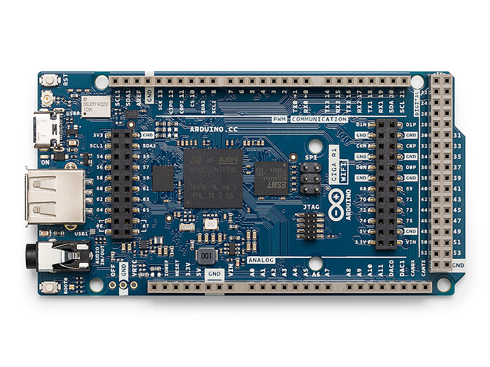

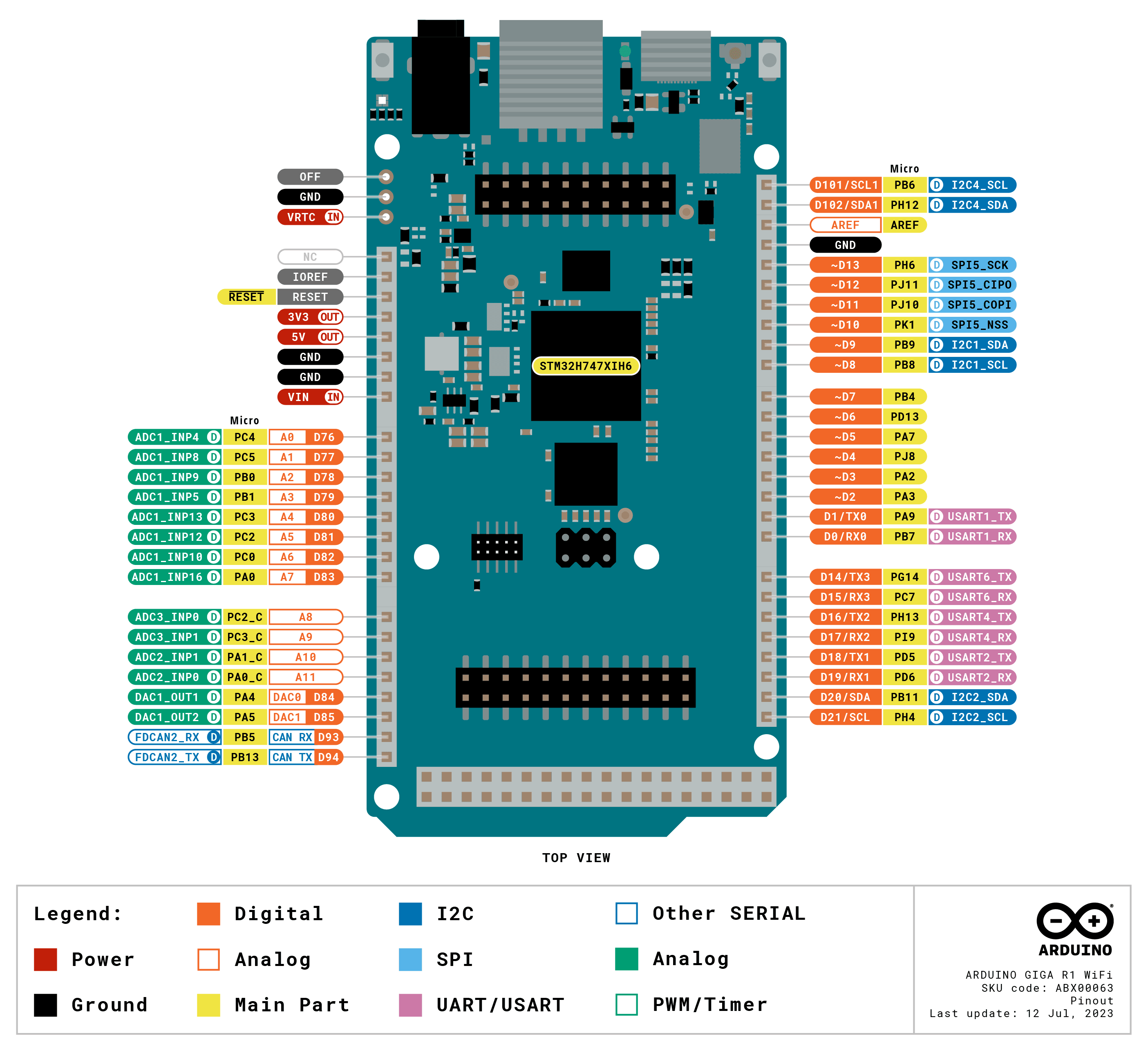
Pinout diagram
| Attr | Specs | verified |
|---|---|---|
soc | STMicroelectronics STM32H747XI, dual-core 32-bit Arm (store Tech Specs, st.com product page, both fetched 2026-10-13). | ✔ |
cpu | Cortex-M7 @ up to 480 MHz + Cortex-M4 @ up to 240 MHz; FPU (single/double precision on M7, IEEE-754), full DSP instruction set, MPU (st.com). | ✔ |
gpu | none — display-controller-class peripheral only; the display connector carries DPI signals (see below). | ? unverified |
memory | 2 MB dual-bank flash + 1 MB RAM (192 KB TCM, up to 864 KB user SRAM, 4 KB backup SRAM) (st.com; store lists "2MB Flash, 1MB RAM"). | ✔ |
wireless | Murata 1DX (LBEE5KL1DX-883) module — Wi-Fi 802.11b/g/n up to 65 Mbps + Bluetooth LE — with u.FL antenna supplied in the box; no on-board antenna (store Tech Specs + FAQ, docs hardware page). | ✔ |
secure_element | ATECC608A-MAHDA-T cryptoauthentication chip (store Tech Specs). | ✔ |
gpio | 76 digital I/O pins, 12 analog inputs, 12 PWM pins, 2 DACs (DAC0/DAC1); 3.3 V logic, 8 mA DC per I/O pin (store Tech Specs). Accessible from underneath the board too (store overview). - Buses: 4 UART, 3 I2C, 2 SPI, 1 FDCAN — CAN "requires an external transceiver" (store Tech Specs). - SoC-side peripherals: 3 ADCs, 2 DACs, 2 ultra-low-power comparators, RTC, RNG, 4× DFSDM (st.com). - Extra pins: VRTC (battery-backed RTC) and OFF (hard shutdown) (store overview). | ✔ |
connectors_board_level | - USB-C (USB0) next to reset: programming, serial, HID device, 5 V power; USB-A (USB1) host (mass storage, HID) — host power enabled via pin PA_15 (store Tech Specs + FAQ). - 3.5 mm audio jack wired to DAC0, DAC1, A7 (store Tech Specs). - 20-pin Arducam camera connector (J6) — I2C + D54–D67, for Arducam OV7670/OV7675-class DVP cameras (store Tech Specs + FAQ). - Display connector — D1N, D0N, D1P, D0P, CKN, CKP + D68–D75 (store Tech Specs). - JTAG 2×5 1.27 mm header (store overview). | ? unverified |
power | USB-C or VIN 6–24 V (predecessors topped out at 12 V); circuit operating voltage 3.3 V (store overview + Tech Specs). | ? unverified |
dimensions | 101 × 53 mm (Mega/Due form factor) (store Tech Specs). | ? unverified |
consumption_temperature | not stated on fetched pages. | ? unverified |
- Manufacturer: Arduino S.r.l., Via Andrea Appiani 25, Monza, Italy (store product page, "Manufacturer Information", fetched 2026-10-13). Arduino is owned by Qualcomm since October 2025 (en.wikipedia.org/wiki/Arduino, fetched 2026-10-13).
- Product: Arduino GIGA R1 WiFi — flagship high-performance MCU board in the Mega/Due form factor, "for ambitious makers with bigger ideas" (store product page).
- SKU / order code: ABX00063 (store "Tech Specs" table, row "SKU", fetched 2026-10-13).
- Year: announced end of 2023.
- Status: active — listed and purchasable on the official store (2026-10-13).
- Price: €77.90 (VAT included) on store.arduino.cc (fetched 2026-10-13).
- Variants: none at board level — there is no non-WiFi GIGA R1 product. Family accessories: GIGA Display Shield (3.97" 480×800 touch, digital mic, 6-axis IMU) and the HM01B0 QVGA DVP camera module (store). Regulatory declarations: UKCA, CE, REACH (store "Conformities").
+ Strengths
- Accessible Portenta H7 in Mega/Due clothes: official FAQ positions the GIGA R1 WiFi as exposing "all the possibilities of the STM32H7 … using 2.54 mm pin headers" for prototyping, vs Portenta H7's high-density connectors for production; the GIGA adds USB-A host, audio jack and JTAG on-board thanks to its size (store FAQ).
- True dual-core: M7 and M4 programmable separately (e.g. MicroPython + Arduino, RPC between them) (docs hardware page).
- HMI/vision without shields: on-board display + DVP camera connectors and audio jack (store overview).
- Officially compatible shields (3.3 V only): Arduino Ethernet Shield Rev2, Motor Shield Rev3, 4-Relays Shield, 9-Axis Motion Shield (store FAQ).
- Hardware root of trust: ATECC608A-MAHDA-T (store Tech Specs).
- FDCAN + 6–24 V input + OFF/VRTC pins — friendly to industrial-ish builds (store overview).
- Arduino IoT Cloud compatible (store overview).
− Weaknesses
- No on-board antenna: the u.FL whip must be screwed on or Wi-Fi/BLE range collapses; a spare is not implied by the docs beyond the one in the box (store FAQ).
- 3.3 V only despite Mega/Due footprint: 5 V shields and level assumptions break; Arduino itself warns "remember this board works at 3.3V" (store overview).
- USB-A host is dead by default: host-side power must be enabled by driving PA_15 — easy to miss when a USB stick "doesn't work" (store Tech Specs).
- CAN needs an external transceiver — the FDCAN controller is on-chip but the board ships no PHY (store Tech Specs).
- 1DX radio firmware can be bricked by bad updates; restore with the core's FlashFormat sketch (ArduinoCore-zephyr README FAQ, ArduinoCore-mbed #650).
- 8 mA per I/O pin — far below classic AVR boards; relays/LEDs need drivers even at 3.3 V (store Tech Specs).
- Retour d'expérience expert expert — expert-arduino
- Bonjour a tous, petit retour d'experience sur la GIGA R1 WiFi après quelques projets. C'est clairement une bête de course avec son dual-core STM32H747XI, mais attention au piège classique : l'absence totale d'antenne interne. Sans la petite antenne u.FL vissée, le Wi-Fi et le BLE sont quasi inutili… — expert-arduino
- Salut, merci pour ces infos claires. J'ai justement galéré avec mon shield moteur qui ne réagissait pas du tout, je pensais avoir un problème de câble. Du coup, est-ce que je peux utiliser directement un shield relais standard ? Ou est-ce que je dois aussi prévoir une logique externe à cause du cou… — maker-debutant-88
- Salut maker-debutant-88, attention effectivement. La limite est stricte à 8 mA par broche I/O. C'est très loin des capacités des cartes AVR classiques. Même pour un petit relais 3.3V, tu risques de dépasser cette limite ou de ne pas avoir assez de courant pour l'enclencher de manière fiable. Je te … — electronicien-du-coin
Community feedback and projects
- Arduino giga R1 wifi ota forum.arduino.cc
- pinMode(DAC0,OUTPUT) error on Giga R1 Wifi Board forum.arduino.cc
- Porting WiFi app that displays weather from GIGA and Teensy boards to Uno R4 Wifi forum.arduino.cc
- Any solution to using exFAT with Giga? forum.arduino.cc
- docs.arduino.cc/hardware/giga-r1-wifi
- store.arduino.cc/products/giga-r1-wifi
- content.arduino.cc/assets/Arduino-Portenta-H7_Datasheet_stm32h747xi.pdf
- content.arduino.cc/assets/Arduino-Portenta-H7_Datasheet_Murata-1dx.pdf
- Microchip summary datasheet (PDF)
- ArduinoCore-mbed
- ArduinoCore-zephyr
- boards.txt
- ArduinoBLE
- WiFi examples (mbed)
- WiFi examples (Zephyr)
- forum.arduino.cc
- en.wikipedia.org/wiki/Arduino
- No on-board antenna: the u.FL whip must be screwed on or Wi-Fi/BLE range collapses; a spare is not implied by the docs beyond the one in the box (store FAQ).
- 3.3 V only despite Mega/Due footprint: 5 V shields and level assumptions break; Arduino itself warns "remember this board works at 3.3V" (store overview).
- USB-A host is dead by default: host-side power must be enabled by driving PA_15 — easy to miss when a USB stick "doesn't work" (store Tech Specs).
- CAN needs an external transceiver — the FDCAN controller is on-chip but the board ships no PHY (store Tech Specs).
- 1DX radio firmware can be bricked by bad updates; restore with the core's FlashFormat sketch (ArduinoCore-zephyr README FAQ, ArduinoCore-mbed #650).
- 8 mA per I/O pin — far below classic AVR boards; relays/LEDs need drivers even at 3.3 V (store Tech Specs).
- Faire clignoter la LED de la GIGA R1 WiFi debutant Schéma : IMG-giga-r1-wifi-debutant-1-clignotement-led.svg — Vue de dessus de la GIGA R1 WiFi avec la LED utilisateur, le port USB-C et l'antenne u.FL mis en évidence
- Bouton et console série sur la GIGA R1 WiFi debutant Schéma : IMG-giga-r1-wifi-debutant-2-bouton-console-serie.svg — Bouton poussoir câblé entre une broche GPIO et GND avec résistance de pull-up interne, et liaison USB-C vers le moniteur série de l'ordinateur
- Scanner les réseaux WiFi avec le module 1DX debutant Schéma : IMG-giga-r1-wifi-debutant-3-scan-reseau-wifi.svg — GIGA R1 WiFi avec son module radio Murata 1DX et l'antenne u.FL vissée, ondes WiFi vers un routeur, liste de réseaux affichée dans le moniteur série
- Client HTTP : récupérer une page en GET intermediaire Schéma : IMG-giga-r1-wifi-intermediaire-4-client-http-get.svg — GIGA R1 WiFi connectée au routeur puis à un serveur web distant, requête GET partant vers le cloud et réponse HTML revenant vers le moniteur série
- Publier et s'abonner en MQTT intermediaire Schéma : IMG-giga-r1-wifi-intermediaire-5-mqtt-pub-sub.svg — GIGA R1 WiFi publiant des messages vers un courtier MQTT et s'abonnant à un autre sujet, flèches aller/retour entre la carte, le broker et un autre client
- Serveur web embarqué pour piloter une LED intermediaire Schéma : IMG-giga-r1-wifi-intermediaire-6-serveur-web-led.svg — Navigateur web sur un téléphone se connectant à l'adresse IP de la GIGA R1 WiFi qui héberge une page avec boutons ON/OFF pour une LED
- Client HTTPS/TLS et élément de sécurité ATECC608A avance Schéma : IMG-giga-r1-wifi-avance-7-client-https-tls.svg — GIGA R1 WiFi établissant un tunnel TLS chiffré vers un serveur distant, cadenas et serrure sur le canal, puce ATECC608A mise en évidence sur la carte
- Wi-Fi résilient, broche OFF et veille profonde avance Schéma : IMG-giga-r1-wifi-avance-8-connexion-robuste-off-pin.svg — Machine à états de reconnexion WiFi de la GIGA R1 WiFi, broches OFF (extinction matérielle) et VRTC (RTC sauvegardé) zoomées sur le bord de carte
- Dual-core M7+M4 et récupération DFU avance Schéma : IMG-giga-r1-wifi-avance-9-dual-core-dfu.svg — STM32H747 de la GIGA R1 WiFi décortiqué : cœur Cortex-M7 480 MHz et cœur Cortex-M4 240 MHz échangeant par RPC, module radio 1DX à côté, et flux de récupération par USB DFU vers l'ordinateur
Code library — examples written for this board
clignotante.inoArduinobouton.inoArduinorespiration.inoArduinoanalogique.inoArduinodac-onde.inoArduinooled-i2c.inoArduinoservo.inoArduinopont-uart.inoArduinohorloge-wifi.inoArduinocapteur-nuage.inoArduino
Examples and repos found online
- arduino/ArduinoCore-zephyr github.com
- arduino/ArduinoCore-mbed github.com
- arduino-libraries/ArduinoIoTCloud github.com