micro:bit V2 (BBC micro:bit v2)
⚡ The essentials in 60 seconds
- soc_target_mcu — Nordic nRF52833 — 32-bit ARM Cortex-M4 @ 64 MHz (with FPU), 512 KB flash, 128 KB RAM, 2.4 GHz BLE radio running Nordic S113 SoftDevice, integrated temperature sensor. (Wikipedia, nRF52833 Product Specification) - No GPU (graphics = 5×5 LED matrix only). - Usable flash in practice: the official MicroPython firmware region is documented as up to 248 KB at 0x00000000 — the rest of the 512 KB is taken by the SoftDevice/CODAL runtime and data-logging/filesystem regions, so "≈256 KB for the app" is the practical figure in the official docs. (microbit-micropython docs — hex format)
- interface_mcu_usb_programmer_not_user_programmable — KL27Z (V2.00) or nRF52820 (V2.2x) running DAPLink (MSC + CDC + CMSIS-DAP HID + WebUSB); it is not connected to the edge-connector GPIOs. (tech.microbit.org/firmware/daplink-interface/)
- display — 5×5 LED matrix (25 LEDs; true 5×5 matrix on V2, unlike V1's scanned 9×3), driven by software multiplexing; also usable as a light sensor. (tech.microbit.org/hardware/schematic/)
- inputs — Buttons A (P0.14) and B (P0.23) + reset (hold reset 3 s = power off on v2, per Wikipedia); touch-sensitive logo (FACE_TOUCH, P1.04); rings P0/P1/P2 support capacitive touch via 10 MΩ external pull-ups. (tech.microbit.org schematic, edge connector, Wikipedia)
- sensors_actuators — combined accelerometer + magnetometer — ST LSM303 (or NXP FXOS8700CQ on some builds) on internal I²C, shared open-drain interrupt COMBINED_SENSOR_INT (P0.25); Knowles MEMS microphone with activity LED (MIC_IN P0.05, RUN_MIC P0.20); magnetic speaker (Jiangsu Huaneng MLT-8530) driven from P0.00 through the interface chip DAC. (Wikipedia, tech.microbit.org schematic pinmap)
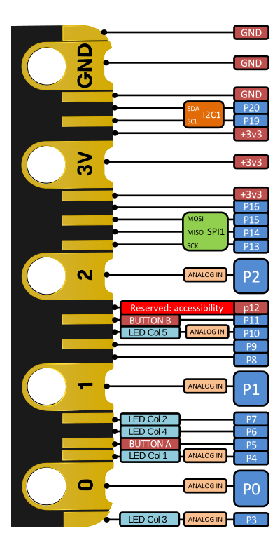
- edge_connector_gpio — 25 strips @ 1.27 mm (80-pin double-sided connector compatible), notched on V2; 5 crocodile-clip rings (P0, P1, P2, 3V, GND). 20 GPIO (P0–P20) at 3.3 V logic: - Analog (ADC): P0, P1, P2 (rings) + P3, P4, P10 (shared with LED columns). - PWM: any pin, but the DAL DynamicPWM driver allows only 3 simultaneous PWM outputs. - Touch: P0, P1, P2 (+ logo). - SPI: P13 SCK / P14 MISO / P15 MOSI; I²C (external): P19 SCL / P20 SDA (4.7 kΩ pull-ups fitted, shared with on-board motion sensor); UART available; NFC possible on P8/P9 (disabled by default). - IO drive: standard drive 0.5–4 mA, high-drive 5 mA per nRF52833 datasheet tables transcribed on the edge-connector page. (tech.microbit.org/hardware/edge-connector/)
- On this board : 9 tutorials · 10 code
The BBC micro:bit V2 stands as a pivotal tool in modern computer education, designed originally by the BBC in partnership with major technology firms like Nordic, NXP, and ARM for the "Make It Digital" campaign in the United Kingdom. Today, it is owned and sold by the Micro:bit Educational Foundation, maintaining its core mission of making programming accessible to students worldwide. Released on October 13, 2020, this second-generation board builds upon the success of the original 2016 model while introducing significant hardware upgrades. It is an open-source, single-board microcontroller, meaning that its design files and schematics are freely available for anyone to study or replicate. The board is specifically tailored for classroom environments, having been distributed for free to Year 7 pupils in UK schools during its initial rollout. While the exact retail price can vary by region and reseller, it is generally positioned as an affordable entry point for learning electronics and coding.
At the heart of the micro:bit V2 is the Nordic nRF52833 system-on-chip, a powerful 32-bit ARM Cortex-M4 processor running at 64 MHz. To put this in perspective, a microcontroller is a small, self-contained computer on a single chip, and the "clock speed" of 64 MHz indicates how many millions of cycles it can perform per second, allowing it to handle complex tasks like processing sensor data and managing wireless communication smoothly. This chip includes a floating-point unit, which helps with mathematical calculations, and comes with 512 KB of flash memory and 128 KB of RAM. However, users should note that not all of this memory is available for their own programs. A significant portion is reserved for the operating system and communication protocols, leaving approximately 248 KB for user applications in the official MicroPython environment. This limitation is a crucial consideration when planning projects that require storing large amounts of data or complex code.
One of the most notable features of the V2 is its connectivity and interaction capabilities. It features Bluetooth Low Energy (BLE) radio, which allows the board to communicate wirelessly with other devices, such as smartphones or other micro:bits, without consuming excessive battery power. This enables creative projects like multiplayer games or remote control applications. The board also includes a built-in microphone and speaker, a significant upgrade from the first version. This audio capability allows students to create projects that respond to sound, such as a clap counter, or projects that produce sound, like a musical instrument or a voice synthesizer. The speaker is connected to pin P0, which means that if you use P0 for other purposes, you may need to disable the speaker to avoid interference. Additionally, the touch-sensitive logo on the front of the board acts as a capacitive touch sensor, allowing users to trigger actions simply by touching the logo, adding a new layer of interactivity to projects.
The user interface of the micro:bit V2 is centered around a 5x5 LED matrix, which consists of 25 individual light-emitting diodes. This grid can display simple graphics, text, and animations. Interestingly, this LED matrix can also function as a light sensor, detecting ambient light levels when the display is not actively showing an image. For physical input, the board has two programmable buttons labeled A and B, which can be used to trigger events in code. The board also includes a combined accelerometer and magnetometer sensor. The accelerometer detects motion and orientation, enabling gestures like shaking or tilting, while the magnetometer acts as a compass, detecting the direction of the Earth's magnetic field. These sensors open up a wide range of possibilities for interactive projects, from step counters to digital compasses.
Programming the micro:bit V2 is designed to be accessible to beginners while remaining powerful enough for advanced users. The board runs no traditional operating system; instead, user programs are flashed as firmware images. The most popular way to start is with MakeCode, a block-based visual programming editor that allows students to drag and drop code blocks to create programs. For those ready to transition to text-based coding, MicroPython is officially supported, offering a simplified version of the Python language that runs directly on the board. Other languages like C++ via the CODAL runtime, Rust, and even Scratch are also supported. Programming is done via a USB connection, where the board appears as a drive on your computer. You simply drag and drop a file onto this drive to update the program, a process that is intuitive and requires no complex software installation.
The micro:bit V2 features an edge connector with 25 pins, providing access to various general-purpose input/output (GPIO) lines. These pins allow the board to interact with external electronic components, such as motors, lights, and sensors. The board operates at 3.3 volts, which is a standard logic level for many modern electronic components. However, users must be careful when connecting external devices, as the board has limited current output capabilities. The official documentation recommends a safe design figure of approximately 190 mA for accessories connected to the edge connector. Power can be supplied via USB, a battery pack connected to the JST-PH connector, or the 3V and GND rings. It is important to note that the 3V ring provides the raw voltage rail, and connecting power sources with incorrect polarity or excessive voltage can damage the board.
Despite its robust design, there are some known limitations and pitfalls to be aware of. For instance, the board supports only three simultaneous PWM (Pulse Width Modulation) outputs, which are used for controlling things like motor speed or servo positions. Attempting to use a fourth PWM channel will silently disable one of the existing ones. Additionally, some pins are shared with internal components; for example, pins P3, P4, P6, P7, P9, and P10 are connected to the LED matrix, so using them for other purposes requires disabling the display first. Similarly, pins P19 and P20 are used for the internal I2C bus connected to the motion sensors, and repurposing them is strongly discouraged. Another common issue is that USB serial communication can drop characters at baud rates above 9600 due to the lack of flow control between the interface chip and the main processor.
The micro:bit V2 is not just a piece of hardware; it is part of a comprehensive educational ecosystem. The Micro:bit Educational Foundation provides extensive documentation, tutorials, and project ideas to help teachers and students get the most out of the board. Projects range from simple dice simulators that use the accelerometer to detect shaking, to complex radio networks where multiple boards communicate with each other. The board’s open-source nature means that the community actively contributes to its development, with regular updates to the firmware and runtime libraries. This ensures that the board remains relevant and capable of supporting new educational initiatives and technological advancements.
In summary, the BBC micro:bit V2 is a versatile and powerful tool for learning electronics and programming. Its combination of sensors, wireless connectivity, audio capabilities, and user-friendly programming interfaces makes it an ideal choice for students and hobbyists alike. While it has some technical limitations that require careful consideration, its strengths far outweigh these drawbacks. By providing a hands-on, interactive way to learn about technology, the micro:bit V2 continues to inspire a new generation of creators and innovators. Whether you are building a simple game, a weather station, or a complex robot, the micro:bit V2 offers the tools and flexibility to bring your ideas to life.
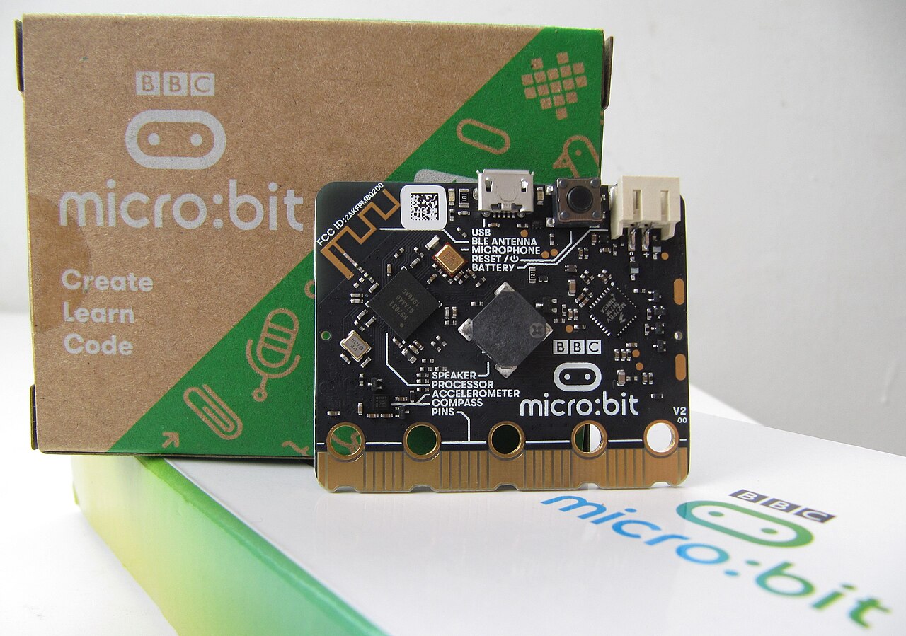
Pinout diagram
| Attr | Specs | verified |
|---|---|---|
soc_target_mcu | Nordic nRF52833 — 32-bit ARM Cortex-M4 @ 64 MHz (with FPU), 512 KB flash, 128 KB RAM, 2.4 GHz BLE radio running Nordic S113 SoftDevice, integrated temperature sensor. (Wikipedia, nRF52833 Product Specification) - No GPU (graphics = 5×5 LED matrix only). - Usable flash in practice: the official MicroPython firmware region is documented as up to 248 KB at 0x00000000 — the rest of the 512 KB is taken by the SoftDevice/CODAL runtime and data-logging/filesystem regions, so "≈256 KB for the app" is the practical figure in the official docs. (microbit-micropython docs — hex format) | ✔ |
interface_mcu_usb_programmer_not_user_programmable | KL27Z (V2.00) or nRF52820 (V2.2x) running DAPLink (MSC + CDC + CMSIS-DAP HID + WebUSB); it is not connected to the edge-connector GPIOs. (tech.microbit.org/firmware/daplink-interface/) | ✔ |
display | 5×5 LED matrix (25 LEDs; true 5×5 matrix on V2, unlike V1's scanned 9×3), driven by software multiplexing; also usable as a light sensor. (tech.microbit.org/hardware/schematic/) | ✔ |
inputs | Buttons A (P0.14) and B (P0.23) + reset (hold reset 3 s = power off on v2, per Wikipedia); touch-sensitive logo (FACE_TOUCH, P1.04); rings P0/P1/P2 support capacitive touch via 10 MΩ external pull-ups. (tech.microbit.org schematic, edge connector, Wikipedia) | ✔ |
sensors_actuators | combined accelerometer + magnetometer — ST LSM303 (or NXP FXOS8700CQ on some builds) on internal I²C, shared open-drain interrupt COMBINED_SENSOR_INT (P0.25); Knowles MEMS microphone with activity LED (MIC_IN P0.05, RUN_MIC P0.20); magnetic speaker (Jiangsu Huaneng MLT-8530) driven from P0.00 through the interface chip DAC. (Wikipedia, tech.microbit.org schematic pinmap) | ✔ |
edge_connector_gpio | 25 strips @ 1.27 mm (80-pin double-sided connector compatible), notched on V2; 5 crocodile-clip rings (P0, P1, P2, 3V, GND). 20 GPIO (P0–P20) at 3.3 V logic: - Analog (ADC): P0, P1, P2 (rings) + P3, P4, P10 (shared with LED columns). - PWM: any pin, but the DAL DynamicPWM driver allows only 3 simultaneous PWM outputs. - Touch: P0, P1, P2 (+ logo). - SPI: P13 SCK / P14 MISO / P15 MOSI; I²C (external): P19 SCL / P20 SDA (4.7 kΩ pull-ups fitted, shared with on-board motion sensor); UART available; NFC possible on P8/P9 (disabled by default). - IO drive: standard drive 0.5–4 mA, high-drive 5 mA per nRF52833 datasheet tables transcribed on the edge-connector page. (tech.microbit.org/hardware/edge-connector/) | ✔ |
connectivity | Bluetooth Low Energy (2.4 GHz, S113 SoftDevice) — no Wi-Fi, no Ethernet. USB micro-B (device only, via interface chip). (Wikipedia) | ✔ |
power | USB 5 V, JST-PH battery connector, or 3V/GND rings / rear pads. V2 has a dedicated on-board regulator rated 300 mA (vs 120 mA via KL26 on V1); docs budget ~30 mA for on-board peripherals and state ≈190 mA available on the edge connector (the overview table on the power page quotes up to 270 mA — the docs themselves are inconsistent; treat 190 mA as the safe design figure). Operating rail 1.7–3.6 V per chip tables; low-Vf diode source-selects USB/battery. (tech.microbit.org/hardware/power-supply/, schematic page) | ✔ |
dimensions | 51.60 mm × 42.00 mm (Wikipedia rounds to "43 mm × 52 mm"); JST connector height 5.5 mm. (tech.microbit.org/hardware/schematic/) | ✔ |
- Manufacturer / developer: Originally designed by the BBC (BBC Learning, BBC R&D) with partners (Nordic, NXP, ARM, Microsoft, Samsung, Farnell element14, Lancaster University…) for the UK "Make It Digital" campaign; today owned and sold under the Micro:bit Educational Foundation (microbit.org). (Wikipedia — Micro Bit, microbit.org)
- Type: Open-source-hardware single-board microcontroller for computer education in UK schools (free distribution to Year 7 pupils in the original programme). (Wikipedia)
- Release: v2 announced/released 13 October 2020 (v1: 10 February 2016). (Wikipedia)
- Launch price: "Available for the same price as the original micro:bit" per Wikipedia's v2 launch summary. (Wikipedia)
- Status: Active — current flagship of the line, sold worldwide via channel partners/resellers (microbit.org/buy/); CODAL v2 target still receiving commits (2026). (github.com/lancaster-university/codal-microbit-v2)
- Variants (board revisions): - V2.00 — interface MCU NXP/Freescale KL27Z (Cortex-M0+, 48 MHz, DAPLink). (tech.microbit.org/firmware/daplink-interface/) - V2.2x (community name "v2.1"/"v2.2") — interface MCU replaced by Nordic nRF52820; separate on-board regulator; DAPLink 0256/0257 factory images. (tech.microbit.org/hardware/schematic/, DAPLink page)
+ Strengths
- Sound I/O on an education board: MEMS mic (with activity LED) + magnetic speaker + built-in sound effects, music/audio/speech APIs (TTS via MARMITE) — unique among classroom boards at this price. (microphone docs, speaker docs, Wikipedia)
- Touch-sensitive logo and touch-capable P0/P1/P2 rings. (tech.microbit.org schematic)
- LED matrix doubles as ambient light sensor (display must be disabled for those pins). (edge connector docs)
- NFC tag capability on P8/P9 (nRF52833 hardware NFC, off by default). (tech.microbit.org schematic)
- BLE "radio" API for peer-to-peer games/chats between boards; radio tutorial in official docs. (MicroPython radio tutorial)
- Power-off by holding reset 3 s + sleep modes (power.reset_reason, sleep APIs) for battery projects. (Wikipedia, power docs)
- Driverless drag-and-drop programming (DAPLink MSC/CDC/WebUSB) — works even after crashing user code, since programming is done by the separate interface MCU. (DAPLink page)
- Open hardware: schematics, BOM and a fully documented reference design for building compatible boards. (tech.microbit.org/hardware/reference-design/, microbit-v2-hardware repo)
- Accessibility ring (P12, "ACCESSIBILITY" function) reserved for assistive-mode support. (edge connector docs)
− Weaknesses
- USB serial drops characters above 9600 baud: only TX/RX are wired between interface and target MCU (no flow control), documented by the Foundation. (tech.microbit.org/firmware/daplink-interface/ — UART connection)
- ADC crosstalk when reading multiple analog pins (reading P1 after P0 returned erratic ~1024 jumps; long-running CODAL issue, closed 2021). (codal-microbit-v2 issue #81)
- Only 3 simultaneous PWM channels — allocating a 4th silently disables an existing one (DAL DynamicPWM limitation). (edge connector docs)
- Pin sharing traps: P3/P4/P6/P7/P9/P10 are wired to the LED matrix (must display.disable before GPIO use); P5/P11 are the buttons; P19/P20 share the internal I²C with the motion sensor ("strongly suggested" not to repurpose them). (edge connector docs)
- Speaker is tied to pin P0: sound output is by default also routed to P0, so using P0 as touch/analog I/O fights the speaker; speaker.off exists but does not disable the P0 audio route. (speaker docs)
- Silent hardware revisions: V2.2x boards (nRF52820 interface, different mic path) need current editors/firmware; old DAPLink images (<0247) lack WebUSB, old interface firmware is the top cause of "won't flash from browser" reports — official firmware-update guide exists. (DAPLink page, microbit.org firmware page)
- Power pitfalls: do not power from USB battery packs (out-of-range voltage / auto-shutoff at low load); 3V ring is the raw V_TGT rail — reverse polarity or >3.6 V there can damage chips (external diode/regulator advised); regulator budget ≈190 mA for accessories. (tech.microbit.org/hardware/power-supply/)
- Flashing failures surface as FAIL.TXT/ASSERT.TXT on the MICROBIT drive; error-code knowledge base maintained by the Foundation. (DAPLink page, error codes KB)
- Crocodile-clip shorts on rings 0/1/2 can disturb the LED display and light-sensing accuracy (guard strips only on 3V/GND). (edge connector docs)
- Retour d'expérience expert expert — expert-microcontroleur
- J'ai repris la micro:bit v2 pour un projet de capteurs. Le SoC nRF52833 est solide, mais attention aux pièges matériels documentés. Le speaker est câblé sur P0, ce qui rend l'usage de cette broche en entrée analogique ou tactile très compliqué, même avec speaker.off. De plus, si vous lisez plusieur… — expert-microcontroleur
- Merci pour ce rappel, j'ai perdu une heure à comprendre pourquoi mes lectures sur P0 étaient bizarres, c'était le conflit avec le haut-parleur. Par contre, j'ai un souci avec la vitesse série. Dès que je dépasse les 9600 bauds, je perds des caractères. C'est normal ? Je pensais que le BLE gérait to… — maker-debutant-42
- Oui, la perte de données au-dessus de 9600 bauds est due à l'absence de contrôle de flux matériel entre le KL27 et le nRF52833, c'est documenté officiellement. Pour l'alimentation sur le pin 3V, prudence absolue : c'est le rail brut V_TGT. La doc déconseille fortement les packs de batteries USB à c… — bricoleur-silicium
Community feedback and projects
- Micro:bit V2 Review - A Must-Have For Every Classroom electromaker.io
- Updated 4x faster BBC micro:bit includes speaker and mic hexus.net
- LED current on BBC micro:bit electronics.stackexchange.com
- Should I use a Micro:bit or Arduino or something else? electronics.stackexchange.com
- FXOS8700CQ pdf
- KL27 pdf
- tech.microbit.org
- hardware
- edge connector & pinout
- power supply
- schematics & pinmap
- DAPLink/interface firmware
- reference design
- microbit.org
- getting started
- firmware updates
- projects
- buy/resellers
- nRF52833 Product Specification
- PDF v1.2 used by tech.microbit.org
- KL27
- FXOS8700CQ
- microbit-foundation/microbit-v2-hardware
- V2.00 schematic PDF
- V2.21 nRF52820 schematic
- lancaster-university/codal-microbit-v2
- microbit-v2-samples
- microbit-foundation/micropython-microbit-v2
- bbcmicrobit/micropython
- v2 docs
- microbit-foundation/DAPLink
- makecode.microbit.org
- python.microbit.org
- Mu editor
- support.microbit.org
- error codes KB
- microbit.pinout.xyz
- Wikipedia: Micro Bit
- USB serial drops characters above 9600 baud: only TX/RX are wired between interface and target MCU (no flow control), documented by the Foundation. (tech.microbit.org/firmware/daplink-interface/ — UART connection)
- ADC crosstalk when reading multiple analog pins (reading P1 after P0 returned erratic ~1024 jumps; long-running CODAL issue, closed 2021). (codal-microbit-v2 issue #81)
- Only 3 simultaneous PWM channels — allocating a 4th silently disables an existing one (DAL DynamicPWM limitation). (edge connector docs)
- Pin sharing traps: P3/P4/P6/P7/P9/P10 are wired to the LED matrix (must display.disable before GPIO use); P5/P11 are the buttons; P19/P20 share the internal I²C with the motion sensor ("strongly suggested" not to repurpose them). (edge connector docs)
- Speaker is tied to pin P0: sound output is by default also routed to P0, so using P0 as touch/analog I/O fights the speaker; speaker.off exists but does not disable the P0 audio route. (speaker docs)
- Silent hardware revisions: V2.2x boards (nRF52820 interface, different mic path) need current editors/firmware; old DAPLink images (<0247) lack WebUSB, old interface firmware is the top cause of "won't flash from browser" reports — official firmware-update guide exists. (DAPLink page, microbit.org firmware page)
- Power pitfalls: do not power from USB battery packs (out-of-range voltage / auto-shutoff at low load); 3V ring is the raw V_TGT rail — reverse polarity or >3.6 V there can damage chips (external diode/regulator advised); regulator budget ≈190 mA for accessories. (tech.microbit.org/hardware/power-supply/)
- Flashing failures surface as FAIL.TXT/ASSERT.TXT on the MICROBIT drive; error-code knowledge base maintained by the Foundation. (DAPLink page, error codes KB)
- Crocodile-clip shorts on rings 0/1/2 can disturb the LED display and light-sensing accuracy (guard strips only on 3V/GND). (edge connector docs)
- Afficher du texte sur la matrice LED 5×5 debutant Schéma : IMG-microbit-v2-debutant-1-microbit-v2-afficher-texte.svg — Carte micro:bit V2 vue de face avec la matrice LED 5×5 affichant un smiley, câble micro-USB à côté
- Réagir aux boutons A, B et au pad tactile du logo debutant Schéma : IMG-microbit-v2-debutant-2-microbit-v2-boutons-ab.svg — micro:bit V2 avec doigts appuyant sur les boutons A et B et doigt touchant le logo tactile, flèches de liaison vers la matrice LED
- Détecter l'inclinaison et les gestes avec l'accéléromètre debutant Schéma : IMG-microbit-v2-debutant-3-microbit-v2-inclinaison-accelerometre.svg — micro:bit V2 inclinée avec flèches de mouvement, icône secouer et flèches haut/bas/gauche/droite autour de la carte
- Boussole numérique avec le magnétomètre intermediaire Schéma : IMG-microbit-v2-intermediaire-1-microbit-v2-boussole-magnetometre.svg — micro:bit V2 à plat avec rose des vents au-dessus, aiguille pointant vers le N et chiffre de cap affiché sur la matrice LED
- Communication entre deux micro:bit avec le module radio intermediaire Schéma : IMG-microbit-v2-intermediaire-2-microbit-v2-radio-communication.svg — deux micro:bit V2 face à face avec ondes radio entre elles, message « SOS » transitant de la matrice de l'une à l'autre
- Se connecter en BLE UART depuis un smartphone intermediaire Schéma : IMG-microbit-v2-intermediaire-3-microbit-v2-ble-uart.svg — smartphone affichant une application série Bluetooth à côté d'une micro:bit V2, flux de données BLE entre les deux et matrice LED affichant un message reçu
- Mesurer le niveau sonore avec le micro MEMS avance Schéma : IMG-microbit-v2-avance-1-microbit-v2-micro-niveau-sonore.svg — micro:bit V2 avec micro MEMS en gros plan sur la face avant, ondes sonores arrivant vers la carte et barre de niveau de 5 LED de la matrice
- Piloter le haut-parleur : sons, mélodies et voix avance Schéma : IMG-microbit-v2-avance-2-microbit-v2-haut-parleur-musique.svg — micro:bit V2 avec haut-parleur magnétique en gros plan, notes de musique sortant de la carte et route audio vers la broche P0 indiquée
- Low-power : extinction, sommeil et réveil avance Schéma : IMG-microbit-v2-avance-3-microbit-v2-low-power-sommeil-reveil.svg — micro:bit V2 alimentée par une pile JST, icône lune de sommeil sur la matrice, bouton A et pictogramme mouvement entourés comme sources de réveil
Code library — examples written for this board
coeur.pyMicroPythonboutons.pyMicroPythonpodometre.pyMicroPythonlumiere.pyMicroPythonmusique.pyMicroPythonradio_ping.pyMicroPythonboussole.pyMicroPythonservo.pyMicroPythonneopixel.pyMicroPythonjournal.pyMicroPython
Examples and repos found online
- lancaster-university/codal-microbit-v2 github.com
- microbit-foundation/micropython-microbit-v2 github.com
- microsoft/pxt-microbit github.com