Arduino MKR GSM 1400
⚡ The essentials in 60 seconds
- mcu — Microchip (ex-Atmel) ATSAMD21G18A — build flag -D__SAMD21G18A__, board entry mkrgsm1400 in ArduinoCore-samd boards.txt: (retrieved 2026-10-13).
- cpu — 1 × Arm Cortex-M0+, 32-bit, 48 MHz (build.mcu=cortex-m0plus, build.f_cpu=48000000L, same boards.txt). 256 KB flash, 32 KB SRAM (SAM D21 description in the launch post,
- gpu — none (microcontroller board).
- storage — internal 256 KB flash only (no SD, no external memory).
- cellular_radio — u-blox SARA-U201 module ("a SARAU201 GSM module", archived official store page also named on Per the archived u-blox SARA-U2 series page ( - GSM/GPRS/EDGE quad-band (850/900/1800/1900 MHz), - UMTS/HSDPA bands 800, 850, 900, 1900, 2100 MHz (global coverage), - data rates 7.2 Mbit/s DL (HSDPA) / 5.76 Mbit/s UL (HSUPA), - 3G operation with 2G fallback ("operates in 3G with a 2G fallback", MKRGSM library docs
- wifi_bluetooth_ethernet_gnss — none. (The SARA-U2 family supports "GNSS via modem" on some variants, but the board exposes no GNSS feature; treat as not available.)
- On this board : 9 tutorials · 10 code
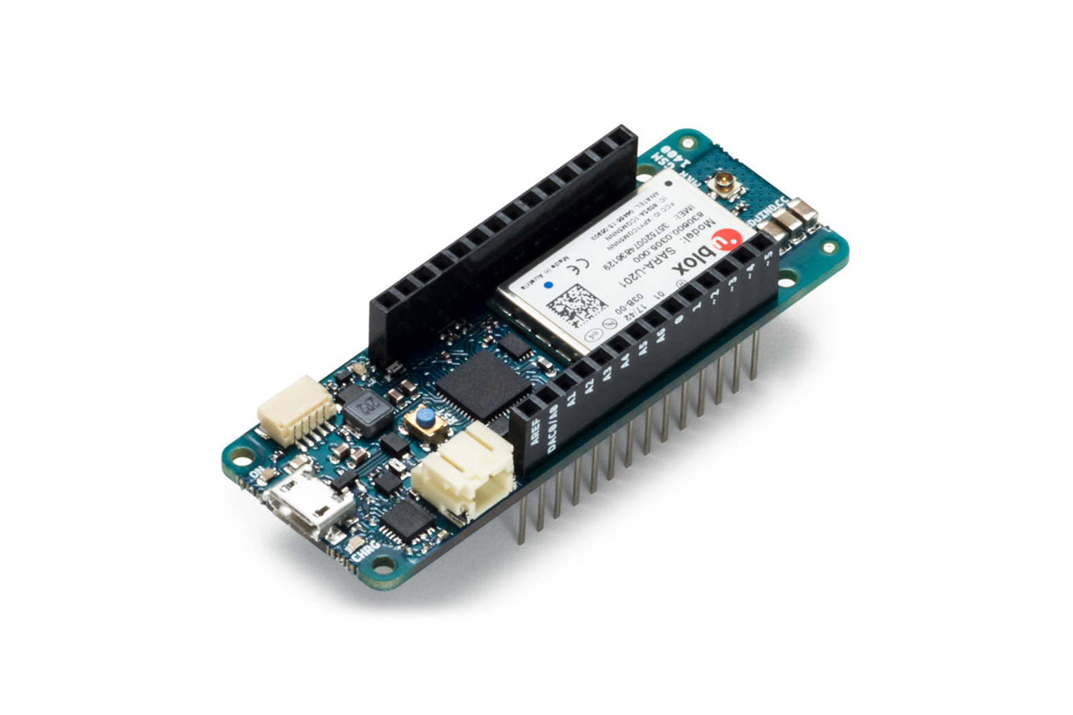
The Arduino MKR GSM 1400 is a compact development board designed to bring cellular connectivity to the Internet of Things, allowing projects to communicate over mobile networks without relying on local Wi-Fi or Ethernet infrastructure. Announced in September 2017, this board belongs to the MKR family, a series of small, credit-card-sized boards that share a common pinout and form factor, making it easy to stack shields or connect to other MKR-compatible accessories. At its core, the board is driven by the Microchip ATSAMD21G18A microcontroller, which is based on an Arm Cortex-M0+ processor running at 48 MHz. For those unfamiliar with these terms, the Cortex-M0+ is a 32-bit processor architecture known for its efficiency and low power consumption, ideal for battery-powered devices. It operates with 256 KB of flash memory for storing the program code and 32 KB of SRAM for temporary data handling. While this is significantly less memory than a typical computer or even a Raspberry Pi, it is sufficient for lightweight tasks such as reading sensors, processing data, and sending it over the network. The board does not include a Graphics Processing Unit, as it is a microcontroller rather than a single-board computer, meaning it is not intended for displaying graphics or running complex operating systems.
The defining feature of the MKR GSM 1400 is its cellular radio module, the u-blox SARA-U201. This module provides global coverage by supporting both 2G and 3G networks. Specifically, it operates on GSM/GPRS/EDGE quad-band frequencies (850, 900, 1800, and 1900 MHz) and UMTS/HSDPA bands (800, 850, 900, 1900, and 2100 MHz). This dual-mode capability allows the device to connect to 3G networks for faster data transfer, with a maximum download speed of 7.2 Mbit/s, while automatically falling back to 2G networks if 3G coverage is unavailable. It is important to note that the SARA-U201 is the global variant of the SARA-U2 family; regional versions exist but are not fitted to this specific board. A common misconception in community discussions is that the board uses a u-blox TOBY-L210 module, but this is incorrect, as the TOBY-L2 series is an LTE Cat 4 line, whereas the MKR GSM 1400 relies on the older SARA-U201 technology. The board requires an external antenna, connected via a small U.FL connector, to communicate with cell towers, and users are advised not to mount the antenna on metallic surfaces to avoid signal interference.
Power management is a critical aspect of this board’s design. It features an integrated power management integrated circuit, the TI BQ24195L, which handles charging for a 3.7 V Lithium Polymer (LiPo) battery and automatically switches between power sources. The board can be powered via USB, an external Vin input ranging from 5 to 12 volts, or the battery itself. However, a crucial operational constraint is that the cellular radio requires significant bursts of current during transmission, which can exceed what a standard USB port can supply. Therefore, it is mandatory to connect a LiPo battery with a capacity of at least 1500 mAh at all times. The battery acts as a buffer, supplementing the USB power during these high-demand moments to prevent the board from resetting or shutting down. Without the battery, the board may fail to maintain a stable cellular connection. The board also includes a dedicated pin for monitoring battery voltage, allowing sketches to check power levels and enter low-power sleep modes when necessary. The design supports very low power consumption, dropping from several milliamps to just a few microamps when the modem and cryptographic chip are powered down.
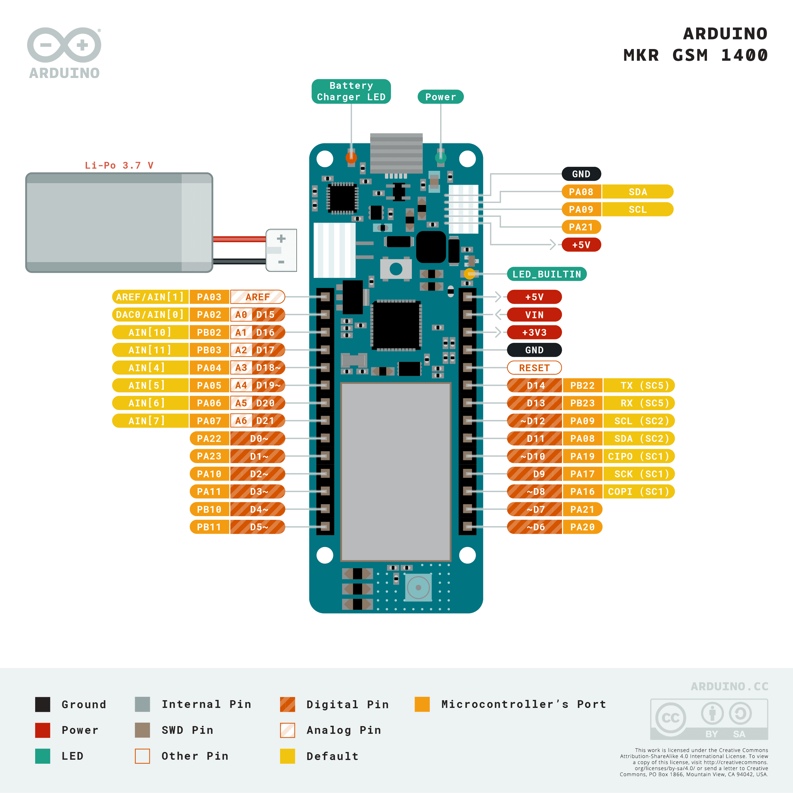
In terms of connectivity and interfaces, the MKR GSM 1400 offers a versatile set of general-purpose input/output pins. It provides eight digital I/O pins, seven analog inputs, and one analog output via a digital-to-analog converter. Twelve of the digital pins are capable of Pulse Width Modulation, a technique used to simulate analog signals for controlling things like motor speed or LED brightness. The board also supports standard communication protocols including I2C, SPI, and UART, allowing it to connect to a wide variety of sensors and peripherals. Notably, it includes a dedicated UART interface for the cellular modem, complete with flow control lines, ensuring reliable communication between the microcontroller and the radio module. Security is another key feature, with an onboard ATECC508A crypto chip. This hardware security module stores private keys securely, enabling encrypted communications over the cellular network using TLS protocols. This is essential for IoT applications where data privacy and device authentication are required, such as connecting to cloud services like AWS IoT or Arduino Cloud.
Despite its capabilities, the MKR GSM 1400 is currently marked as End of Life by Arduino, meaning it is no longer in active production or support. This status is significant given the global retirement of 3G networks by many carriers, a trend that began in the early 2020s and continues to accelerate. As 3G networks are phased out, the board’s primary high-speed data capability becomes unavailable, forcing it to rely on 2G/GPRS networks, which are also being deprecated in various regions. Additionally, the official library for the board, MKRGSM, has not been updated since 2019, which may lead to compatibility issues with modern cloud endpoints or security certificates. Users should also be aware that the board does not include audio hardware, so while it can control voice calls (dialing and hanging up), it cannot transmit or receive voice audio, as there is no microphone or speaker. For developers, the board is programmed using the Arduino IDE with the SAMD core, and it uses a specific bootloader that can be accessed by double-pressing the reset button. While it remains a functional tool for legacy projects or educational purposes, new designs should consider newer cellular technologies like LTE-M or NB-IoT, which are designed for long-term network availability and lower power consumption.
Pinout diagram
| Attr | Specs | verified |
|---|---|---|
mcu | Microchip (ex-Atmel) ATSAMD21G18A — build flag -D__SAMD21G18A__, board entry mkrgsm1400 in ArduinoCore-samd boards.txt: (retrieved 2026-10-13). | ✔ |
cpu | 1 × Arm Cortex-M0+, 32-bit, 48 MHz (build.mcu=cortex-m0plus, build.f_cpu=48000000L, same boards.txt). 256 KB flash, 32 KB SRAM (SAM D21 description in the launch post, | ✔ |
gpu | none (microcontroller board). | ? unverified |
storage | internal 256 KB flash only (no SD, no external memory). | ? unverified |
cellular_radio | u-blox SARA-U201 module ("a SARAU201 GSM module", archived official store page also named on Per the archived u-blox SARA-U2 series page ( - GSM/GPRS/EDGE quad-band (850/900/1800/1900 MHz), - UMTS/HSDPA bands 800, 850, 900, 1900, 2100 MHz (global coverage), - data rates 7.2 Mbit/s DL (HSDPA) / 5.76 Mbit/s UL (HSUPA), - 3G operation with 2G fallback ("operates in 3G with a 2G fallback", MKRGSM library docs | ✔ |
wifi_bluetooth_ethernet_gnss | none. (The SARA-U2 family supports "GNSS via modem" on some variants, but the board exposes no GNSS feature; treat as not available.) | ? unverified |
antenna | external GSM antenna on a U.FL (micro U.FL) connector; Arduino warns not to mount the antenna on a metallic surface (archived store page, URL above). | ? unverified |
sim | micro-SIM form factor. | ? unverified |
usb | full-speed USB device + embedded host capability ("Full-Speed USB Device and embedded Host", archived store page). USBident: VID 0x2341, PID 0x8052 (bootloader PID 0x0052) — boards.txt. | ? unverified |
gpio_mkr_pinout_3_3_v_logic_launch_post | - 8 digital I/O D0–D7 (D6 = LED_BUILTIN), 8 external interrupt pins (launch post; pin table in variants/mkrgsm1400/variant.cpp - 12 PWM-capable outputs (launch post; PWM channels on D0–D8 and A3/A4 per variant.cpp). - 7 analog inputs A0–A6, 1 analog output (DAC) on A0/DAC0 (NUM_ANALOG_INPUTS 7, NUM_ANALOG_OUTPUTS 1, ADC_RESOLUTION 12 — variants/mkrgsm1400/variant.h - I2C Wire SDA=11/SCL=12 (SERCOM2); SPI MOSI=8/SCK=9/MISO=10 (SERCOM1); UART Serial1 RX=13/TX=14 (SERCOM5); I2S pins defined (variant.h). - Dedicated modem UART Serial2/SerialGSM with RTS/CTS flow control (SERCOM4, pins 26–29) plus GSM_RESETN (31) and GSM_DTR (35) (variant.h/variant.cpp). - Battery voltage sense ADC_BATTERY (pin 32) and PMIC_IRQ (pin 30) (variant.h). | ✔ |
power | 3.7 V LiPo on battery pads with on-board TI BQ24195L charger/PMIC on I2C (-DUSE_BQ24195L_PMIC in boards.txt; PMIC init/charge-control code in variant.cpp); Vin 5–12 V external input; USB 5 V; automatic power-source switching; runs with or without battery (launch post). | ? unverified |
typical_consumption | MCU sleep and crypto-chip power-down take the design from "several mA to a few µA" (Arduino maintainer note, ECC508 alone drops 800 µA → 6 µA when powered down). | ✔ |
size | 67.64 × 25 mm (launch post). | ? unverified |
- Manufacturer: Arduino (product created under Arduino AG; the company itself was acquired by Qualcomm in October 2025 — retrieved 2026-10-13).
- Announced: 2017-09-25, unveiled at World Maker Faire New York, pre-orders opened the same week on the Arduino Store — (retrieved 2026-10-13).
- Status: End of Life — the official product page is flagged "End of Life" and the store URL now redirects to it: (retrieved 2026-10-13).
- Price: US $69.90 listed on the official Arduino Store (US) product page, archived snapshot 2019-03-04 (SKU MKRGSM1400WANT, data-price="69.9"): (retrieved 2026-10-13).
- Variants: one board SKU (MKR form factor). The cellular module itself, the u-blox SARA-U201, is the global-coverage variant of the SARA-U2 family (regional siblings SARA-U260/U270/U280 exist but are not fitted to official board variants) — (retrieved 2026-10-13).
- Common confusion to avoid: some community sources (and third-party library notes) describe the board as carrying a u-blox TOBY-L210. That is wrong: the TOBY-L2 family is an LTE Cat 4 line ("TOBY-L210 — LTE/HSPA+/GSM module for Europe/Asia", Arduino's own store page and docs page both state SARA-U201 (sources above).
+ Strengths
- Global 2G/3G cellular in the MKR shield form factor — the only MKR with HSPA data, SMS and circuit-switched voice calls (make/receive, DTMF) plus GPRS/UDP/NTP/ping APIs (MKRGSM readme: "do most of the operations you can do with a GSM phone").
- ATECC508A ("ECC508") crypto chip for secure key storage — named on the official product page ( and used in Arduino's official AWS IoT samples via ArduinoECCX08 + BearSSLClient with the MKRGSM client ("private key stored in the ATECC508A",
- TLS over cellular two ways: modem-native SSL profiles (GSMSSLClient, root-CA management, MKRGSM CHANGELOG 1.3.0/1.4.x) or host-side BearSSL using the ECC508 for client certificates.
- BQ24195L PMIC with LiPo charging, power-source auto-switching, charge/battery fault interrupts (PMIC_IRQ_PIN), plus battery-voltage ADC (ADC_BATTERY) — boards.txt + variant.h/variant.cpp.
- Low-power design path: modem reset held at boot to save power when unused ("put GSM modem in reset on start to conserve power", variant.cpp), documented sleep modes down to a few µA (ArduinoIoTCloud issue #73).
- Ethernet/WiFi-style API: MKRGSM deliberately mirrors the Ethernet/WiFi101 client/server classes for easy porting (docs/readme.md).
- Arduino SIM / IoT Cloud integration from launch-era tooling (examples support the Arduino Create "secret tab", MKRGSM CHANGELOG 1.0.1; Arduino SIM rollout
− Weaknesses
- USB power is not sufficient — LiPo mandatory in practice: "This is in excess of what can be sourced by a standard USB port, so it is MANDATORY to have a 1500 mAh or higher LiPo battery plugged all the time, the current provided by the USB port will be supplemented by the battery" (archived official store page,
- Power LED glows on battery power on MKR GSM 1400 / WiFi 1010 / NB 1500 — reported, unresolved:
- Bootloader ignores the SAMD security bit: flash (including the SIM PIN hardcoded by sketches) remains readable via bossac even with security enabled —
- I2C/PMIC hang: SERCOM::startTransmissionWIRE can freeze the core on I2C bus trouble; the board's early boot talks to the BQ24195L PMIC over I2C, so a faulty PMIC/bus bricks boot — PMIC init itself was reworked in
- Carrier blocks incoming connections: GSMServer is useless on most operators ("A number of network operators do not allow for incoming connections from the public internet", MKRGSM docs/readme.md).
- TLS trust-store churn: bundled root CA had to be swapped (Amazon Root CA 1 → Starfield, then back) as certificates rotated — MKRGSM CHANGELOG 1.4.0/1.4.1; old library versions fail against modern endpoints.
- Library frozen / network sunset risk: MKRGSM last release 1.4.2 (2019-06-18) and the board is EOL, while 3G networks are being retired worldwide — Verizon ended 3G on 2022-12-31, T-Mobile on 2022-07-01, and "19 operators in 14 countries plan to phase out 3G by 2025" in Europe ( retrieved 2026-10-13). The board falls back to 2G/GPRS, which is itself being phased out in some countries.
- No audio hardware for voice calls: the modem handles calls but the board has no mic/speaker, so voice-call examples only control call state (MKRGSM examples list; no audio codec in variant.h).
- Retour d'expérience expert expert — expert-arduino
- Petit retour d'experience sur la MKR GSM 1400, qui est malheureusement en fin de vie. Le point fort reste son integrite : c'est la seule carte MKR avec HSPA, SMS et appels vocaux. La puce ATECC508A est top pour la sécurité des cles via BearSSL. Par contre, attention au problème majeur documente : l… — expert-arduino
- Je confirme le souci d'alimentation, c'est très frustrant quand on debute. Mais ma vraie question porte sur la librarie MKRGSM. Je vois qu'elle est figee a la version 1.4.2 et que la carte est EOL. Avec la fermeture progressive des réseaux 3G partout dans le monde, est-ce que quelqu'un a pu tester … — maker-slow
- Pour le fallback 2G, ca depend vraiment de ton operateur local, mais le risque est reel vu que certains pays coupent aussi le 2G. Concernant la lecture du flash via bossac, oui c'est un bug connu non corrige car la carte est abandonnee. Si tu stockes le PIN SIM en dur dans le code, c'est une faille… — hacker-0x1
Community feedback and projects
- Mkr gsm 1400 how to tell if USB forum.arduino.cc
- WDTZero and RTCZero coexistence on SAMD21 board (MKR GSM 1400) forum.arduino.cc
- Chrg LED leuchtet und gsm code funktioniert nicht, arduino mkr gsm 1400 forum.arduino.cc
- Edge Control + MKR GSM 1400 + RESET button => frozen boards forum.arduino.cc
- SARA-U2_DataSheet_(UBX-13005287).pdf datasheet
- Official product page (EOL notice, ECC508 + SARA-U201 mention)
- Launch announcement (specs, size, power)
- Archived official store page (price $69.90, "LiPo ≥1500 mAh mandatory", U.FL antenna, SARA-U201)
- Board definition
- Pin variant
- MKRGSM library + API docs + examples
- u-blox SARA-U2 series product page (archived; u-blox sold its cellular line to Trasna in 2025, so live u-blox.com produc
- SARA-U2 datasheet reference UBX-13005287 (live u-blox PDF 404; use Wayback copies of SARA-U2_DataSheet_(UBX-13005287).pd
- u-blox cellular AT-commands manual (still live on u-blox.com)
- Crypto chip stack
- Crypto chip stack
- Alternatives
- Alternatives
- USB power is not sufficient — LiPo mandatory in practice: "This is in excess of what can be sourced by a standard USB port, so it is MANDATORY to have a 1500 mAh or higher LiPo battery plugged all the time, the current provided by the USB port will be supplemented by the battery" (archived official store page,
- Power LED glows on battery power on MKR GSM 1400 / WiFi 1010 / NB 1500 — reported, unresolved:
- Bootloader ignores the SAMD security bit: flash (including the SIM PIN hardcoded by sketches) remains readable via bossac even with security enabled —
- I2C/PMIC hang: SERCOM::startTransmissionWIRE can freeze the core on I2C bus trouble; the board's early boot talks to the BQ24195L PMIC over I2C, so a faulty PMIC/bus bricks boot — PMIC init itself was reworked in
- Carrier blocks incoming connections: GSMServer is useless on most operators ("A number of network operators do not allow for incoming connections from the public internet", MKRGSM docs/readme.md).
- TLS trust-store churn: bundled root CA had to be swapped (Amazon Root CA 1 → Starfield, then back) as certificates rotated — MKRGSM CHANGELOG 1.4.0/1.4.1; old library versions fail against modern endpoints.
- Library frozen / network sunset risk: MKRGSM last release 1.4.2 (2019-06-18) and the board is EOL, while 3G networks are being retired worldwide — Verizon ended 3G on 2022-12-31, T-Mobile on 2022-07-01, and "19 operators in 14 countries plan to phase out 3G by 2025" in Europe ( retrieved 2026-10-13). The board falls back to 2G/GPRS, which is itself being phased out in some countries.
- No audio hardware for voice calls: the modem handles calls but the board has no mic/speaker, so voice-call examples only control call state (MKRGSM examples list; no audio codec in variant.h).
- Faire clignoter la LED embarquée et lire la batterie debutant Schéma : IMG-mkr-gsm-1400-debutant-1-mkrgsm-led-clignotant.svg — Vue de dessus de la carte MKR GSM 1400 avec la LED embarquée (broche D6) et les pads batterie LiPo mis en évidence.
- Bouton poussoir et console USB debutant Schéma : IMG-mkr-gsm-1400-debutant-2-mkrgsm-bouton-console.svg — Carte MKR GSM 1400 sur breadboard avec un bouton poussoir entre la broche D2 et la masse, câble micro-USB relié à un ordinateur affichant la console série.
- Lire un capteur analogique sur A1 debutant Schéma : IMG-mkr-gsm-1400-debutant-3-mkrgsm-capteur-analogique.svg — MKR GSM 1400 avec un potentiomètre alimenté en 3,3 V dont le curseur est relié à l'entrée analogique A1, tension affichée sur la console USB.
- Se connecter à un réseau GPRS (APN, signal, enregistrement) intermediaire Schéma : IMG-mkr-gsm-1400-intermediaire-1-mkrgsm-reseau-gprs.svg — MKR GSM 1400 avec antenne externe déployée sur connecteur U.FL, carte micro-SIM insérée, et à l'écran l'opérateur détecté avec la puissance du signal.
- Envoyer et recevoir des SMS intermediaire Schéma : IMG-mkr-gsm-1400-intermediaire-2-mkrgsm-sms.svg — MKR GSM 1400 échangeant des SMS avec un téléphone mobile, ondes radio entre l'antenne et le téléphone, message « ALERTE » affiché sur les deux écrans.
- HTTP GET via GPRS intermediaire Schéma : IMG-mkr-gsm-1400-intermediaire-3-mkrgsm-http-get.svg — Requête HTTP GET partant de la MKR GSM 1400 via l'antenne vers une antenne relais puis un serveur web, la réponse s'affichant sur la console USB.
- Publier en MQTT sur le réseau GPRS avance Schéma : IMG-mkr-gsm-1400-avance-1-mkrgsm-mqtt-gprs.svg — MKR GSM 1400 publiant des messages MQTT via l'antenne vers un broker sur Internet, le flux traversant l'antenne relais et un serveur, avec jauges de capteur publiées.
- Sommeil bas courant du module et réveil avance Schéma : IMG-mkr-gsm-1400-avance-2-mkrgsm-sommeil-bas-courant.svg — MKR GSM 1400 sur batterie LiPo endormie (LED éteinte, croissant de lune), une ligne de courant chutant de quelques milliampères vers quelques microampères, bouton de réveil sur D2.
- Diagnostic AT du module et version de firmware avance Schéma : IMG-mkr-gsm-1400-avance-3-mkrgsm-diagnostic-at.svg — Console série affichant des commandes AT envoyées au module SARA-U201 de la MKR GSM 1400 (AT+CSQ, AT+COPS?, AT+CGMR) avec leurs réponses, antenne à côté.
Code library — examples written for this board
gsm-connexion.inoArduinoenvoi-sms.inoArduinohttp-get.inoArduinohttp-post-capteur.inoArduinoheure-gsm.inoArduinoappels.inoArduinobatterie-lipo.inoArduinosleep-gsm.inoArduinogsm_logger.pyPythonconsole-at.shBash
Examples and repos found online
- arduino-libraries/MKRGSM github.com
- arduino/ArduinoCore-samd github.com
- arduino-libraries/ArduinoIoTCloud github.com
- iotconnectivity/iotsmartsim github.com