Arduino Opta (micro PLC, STM32H747)
⚡ The essentials in 60 seconds
- mcu — ST STM32H747XI (board definition says STM32H747XIH6, Zephyr board doc) — dual core: Arm Cortex-M7 @ up to 480 MHz + Cortex-M4 @ up to 240 MHz, 2 MB flash (read-while-write), 1 MB RAM. ST device pages: STM32H747XI product, datasheet PDF, reference manual RM0399.
- storage — 2 MB internal flash + 16 MB QSPI flash (shared between firmware use and data logging).
- security — ATECC608B crypto co-processor (16 protected key/cert slots, secure boot support, unique 72-bit serial).
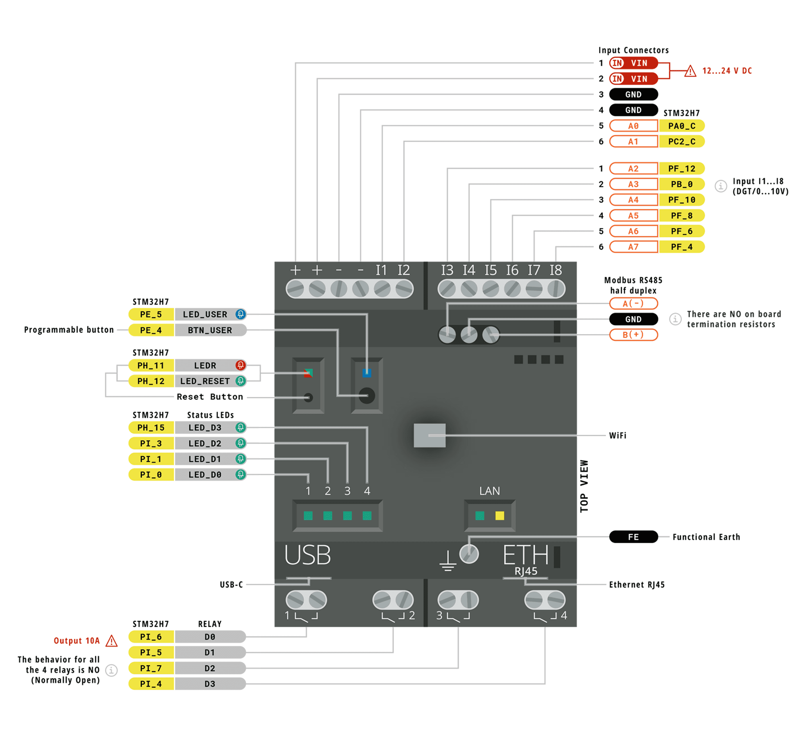
- i_o_screw_terminals_industrial_24_v_world — - 8 multi-function inputs I1…I8 (mapped A0…A7 / PIN_A0…): - Digital mode: 0–24 VDC, VIL ≤ 4.46 V, VIH ≥ 6.6 V, input impedance 8.9 kΩ, 1.12 mA @ 10 V, max frequency 4.5 kHz; overvoltage + reverse-polarity protected. - Analog mode: 0–10 VDC, 12–16-bit user-configurable resolution, LSB 166 µV, accuracy ±5 % (repeatability ±2 %), 10 µs acquisition cycle. - 4 relay outputs OUTPUT1…4 (mapped D0…D3 / RELAY1…RELAY4), Normally-Open SPST, 10 A / 250 VAC (max 400 VAC), 15 A peak (≤10 % duty, ≤0.5 s), rated load AC1 2500 VA / AC15 500 VA, DC1 breaking capacity 10/4/0.3/0.12 A at 24/30/110/220 V, minimum switching load 300 mW (5 V/5 mA), operate/release 6/4 ms, bounce 3 ms NO; mechanical life 10 M operations, electrical life 10 k operations at 10 A resistive. No internal short-circuit protection — external fuse required. Max unshielded output line 100 m. - 4 user LEDs (+1 extra on WiFi), user programmable button, pinhole reset.
- connectivity — 10/100BASE-T Ethernet (all variants, RMII PHY, IEEE 802.3/802.3u, MDIX); RS-485 half-duplex (RS485 & WiFi); Wi-Fi 2.4 GHz 802.11 b/g/n + Bluetooth LE on WiFi (BLE 5.1 in hardware, 4.2 in current firmware); USB-C (host or device, programming/data logging only — cannot power the relay outputs); proprietary expansion port (up to 5 snap-on modules).
- power — 12–24 VDC supply (permissible 10.2–27.6 V), consumption 0.6–2.0 W @12 V / 0.6–2.2 W @24 V. Terminals: 0.5–6 mm² wire, 0.80 Nm torque. Functional-earth terminal provided for fieldbus noise immunity.
- On this board : 9 tutorials · 10 code
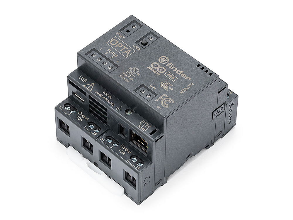
The Arduino Opta represents a significant shift in the landscape of industrial automation, bridging the gap between the accessible, open-source world of maker electronics and the rigorous demands of professional control systems. Released in January 2023, this device is not merely a microcontroller board but a certified micro Programmable Logic Controller (PLC). It was co-designed by Arduino and Finder, an Italian manufacturer renowned for its relays and industrial automation components, ensuring that the hardware meets the durability and safety standards required for factory floors and control cabinets. The Opta is currently available in three distinct variants, all sharing the same robust base module but differing in their communication capabilities. The Opta Lite serves as the entry-level model, while the Opta RS485 adds half-duplex serial communication for connecting to industrial networks. The top-tier Opta WiFi variant includes both RS-485 and wireless connectivity via 802.11 b/g/n Wi-Fi and Bluetooth Low Energy, offering greater flexibility for remote monitoring and integration into Internet of Things ecosystems. Despite some third-party catalogues occasionally referring to confusing naming conventions like "Opta Line" or claiming an IP40 rating, official documentation confirms that all variants feature a plastic DIN-rail enclosure rated IP20, designed for installation inside protected electrical cabinets rather than direct exposure to dust and water.
At the heart of the Opta lies the STMicroelectronics STM32H747XI, a powerful dual-core microcontroller that provides the computational muscle necessary for real-time control tasks. This chip features an Arm Cortex-M7 core running at up to 480 MHz and a secondary Cortex-M4 core at up to 240 MHz. In practical terms, this dual-core architecture allows the device to handle complex logic and communication tasks on the main core while potentially offloading background processes or specific real-time constraints to the secondary core. The system is equipped with 2 MB of internal flash memory and 1 MB of RAM, supplemented by an additional 16 MB of external QSPI flash. This extra storage is particularly useful for data logging, allowing the controller to record sensor readings or operational states directly onto the device or a connected USB drive without needing an external computer. Security is also a priority, with an ATECC608B crypto co-processor integrated to handle secure boot processes and store cryptographic keys, ensuring that firmware updates and communications remain protected against tampering.
The input and output interfaces are designed specifically for the industrial 24-volt environment, eliminating the need for signal conditioning boards that are often required when using standard 5-volt microcontrollers. The Opta features eight multi-function inputs that can accept digital signals ranging from 0 to 24 volts DC. These inputs are robust, offering protection against overvoltage and reverse polarity, which are common issues in industrial wiring. When configured in analog mode, these same inputs can read 0 to 10-volt signals with a user-configurable resolution of up to 16 bits, providing high precision for sensor data such as temperature or pressure readings. On the output side, the board includes four relay outputs. Relays are electromechanical switches that allow a low-voltage control circuit to switch a high-voltage, high-current load. The Opta’s relays are Normally Open SPST (Single Pole Single Throw) contacts rated for 10 amperes at 250 volts AC. This means they can directly control motors, lights, or valves without the need for additional contactors, provided the load is within the specified limits. It is crucial to note that these relays do not have internal short-circuit protection, so external fuses are mandatory in any installation to prevent damage to the device or the wiring.
Connectivity options are extensive, reflecting the device’s role as a gateway between physical machinery and digital networks. All variants include a 10/100BASE-T Ethernet port, which supports standard industrial protocols like Modbus TCP. The RS-485 variants support Modbus RTU, a widely used serial communication protocol in industrial settings. For users needing wireless capabilities, the WiFi variant provides 2.4 GHz Wi-Fi and Bluetooth LE, although it is worth noting that while the hardware supports Bluetooth 5.1, current firmware limitations restrict it to version 4.2. The board also features a USB-C port, but it is important to understand its limitations: USB-C is intended solely for programming the device and data logging. It cannot power the relay outputs or the industrial I/O circuits, which must be supplied by a separate 12 to 24-volt DC power source connected to the screw terminals. This separation ensures that the control logic remains stable even if the programming interface is disconnected.
Programming the Opta offers flexibility for developers of different backgrounds. It supports the standard Arduino programming environment, allowing users to write sketches in C++ using familiar libraries for Ethernet, Modbus, and Wi-Fi. For those more comfortable with traditional industrial automation, the device is fully compatible with the Arduino PLC IDE, which supports the five IEC 61131-3 programming languages, including Ladder Diagram and Structured Text. This dual-programming capability makes the Opta unique, as it allows engineers to leverage the vast Arduino community and open-source libraries while still adhering to industry-standard control logic practices. Additionally, the device supports snap-on expansion modules that can add more digital or analog inputs and outputs, allowing the system to scale as needed. These modules are auto-detected, simplifying the configuration process.
Despite its robust design, there are some considerations for users. The operating temperature range is limited to -20 to +50 degrees Celsius, which is standard for indoor control cabinets but may require derating in hotter environments. The relay contacts have a mechanical life of 10 million operations, but their electrical life is significantly shorter at maximum load, rated for 10,000 cycles at 10 amperes. This means that for applications involving frequent switching of high-current loads, users should consider external contactors to extend the system's lifespan. Furthermore, while the STM32H747 chip supports CAN bus communication, the Opta board does not expose CAN transceivers or terminals, so fieldbus communication is primarily handled via Ethernet and RS-485. The transition from the older Mbed OS core to the newer Zephyr-based core is also underway, offering improved performance and features, though users should be aware of potential migration challenges as this ecosystem matures. Overall, the Arduino Opta stands as a versatile, secure, and powerful tool for modernizing industrial control systems, combining the ease of use of Arduino with the reliability required for professional automation tasks.
Pinout diagram
| Attr | Specs | verified |
|---|---|---|
mcu | ST STM32H747XI (board definition says STM32H747XIH6, Zephyr board doc) — dual core: Arm Cortex-M7 @ up to 480 MHz + Cortex-M4 @ up to 240 MHz, 2 MB flash (read-while-write), 1 MB RAM. ST device pages: STM32H747XI product, datasheet PDF, reference manual RM0399. | ✔ |
storage | 2 MB internal flash + 16 MB QSPI flash (shared between firmware use and data logging). | ? unverified |
security | ATECC608B crypto co-processor (16 protected key/cert slots, secure boot support, unique 72-bit serial). | ? unverified |
i_o_screw_terminals_industrial_24_v_world | - 8 multi-function inputs I1…I8 (mapped A0…A7 / PIN_A0…): - Digital mode: 0–24 VDC, VIL ≤ 4.46 V, VIH ≥ 6.6 V, input impedance 8.9 kΩ, 1.12 mA @ 10 V, max frequency 4.5 kHz; overvoltage + reverse-polarity protected. - Analog mode: 0–10 VDC, 12–16-bit user-configurable resolution, LSB 166 µV, accuracy ±5 % (repeatability ±2 %), 10 µs acquisition cycle. - 4 relay outputs OUTPUT1…4 (mapped D0…D3 / RELAY1…RELAY4), Normally-Open SPST, 10 A / 250 VAC (max 400 VAC), 15 A peak (≤10 % duty, ≤0.5 s), rated load AC1 2500 VA / AC15 500 VA, DC1 breaking capacity 10/4/0.3/0.12 A at 24/30/110/220 V, minimum switching load 300 mW (5 V/5 mA), operate/release 6/4 ms, bounce 3 ms NO; mechanical life 10 M operations, electrical life 10 k operations at 10 A resistive. No internal short-circuit protection — external fuse required. Max unshielded output line 100 m. - 4 user LEDs (+1 extra on WiFi), user programmable button, pinhole reset. | ? unverified |
connectivity | 10/100BASE-T Ethernet (all variants, RMII PHY, IEEE 802.3/802.3u, MDIX); RS-485 half-duplex (RS485 & WiFi); Wi-Fi 2.4 GHz 802.11 b/g/n + Bluetooth LE on WiFi (BLE 5.1 in hardware, 4.2 in current firmware); USB-C (host or device, programming/data logging only — cannot power the relay outputs); proprietary expansion port (up to 5 snap-on modules). | ? unverified |
power | 12–24 VDC supply (permissible 10.2–27.6 V), consumption 0.6–2.0 W @12 V / 0.6–2.2 W @24 V. Terminals: 0.5–6 mm² wire, 0.80 Nm torque. Functional-earth terminal provided for fieldbus noise immunity. | ? unverified |
environment_reliability | −20…+50 °C, IP20, pollution degree 2 (IEC 61010), MTBF 766 205 h (MIL-HDBK-217F @25 °C). RTC keeps time ~10 days without power (NTP sync via Ethernet, or Wi-Fi on AFX00002). | ? unverified |
certifications | cULus, ENEC, FCC, CE, CB, UKCA. | ? unverified |
can_note | the STM32H747 silicon integrates FDCAN controllers (listed in the Zephyr board feature table), but no CAN/CAN FD transceiver or terminals are documented on the Opta board. > | ? unverified |
- Manufacturer: Arduino (Arduino "Pro" / industrial line), co-designed in partnership with Finder®, the Italian relay and industrial-automation manufacturer (arduino.cc/pro/hardware-arduino-opta).
- Year / status: released 2023-01-09 (releaseDate: 2023-01-09 in the official docs metadata, docs-content product.md); still active and sold on the official store as of 2026-10-13.
- Official variants (current, per the collective datasheet AFX00001-AFX00002-AFX00003): | Variant | SKU | RS-485 | Wi-Fi / BLE | Store price (EUR, 2026-10-13) | |---|---|---|---|---| | Opta Lite | AFX00003 | — | — | 156.00 | | Opta RS485 | AFX00001 | half-duplex | — | 171.00 | | Opta WiFi | AFX00002 | half-duplex | 802.11 b/g/n 2.4 GHz + BLE | 206.00 | Prices read from the official store search API (store.arduino.cc/products/opta-lite, opta-rs485, opta-wifi).
- Launch price: >
- ⚠️ About the "Opta Line / Opta Plastic" naming in boards.json: > e arduino/docs-content repository tree. The datasheet explicitly rates the housing as IP20 (plastic DIN-rail enclosure), not IP40 metal. The real product distinction is the three connectivity variants (Lite / RS485 / WiFi), all sharing the same relay-equipped base module. Upstream Zephyr board docs additionally mention an "Opta Advanced" name for the model with the extra user-button LED (Zephyr board doc), which is most likely the WiFi variant. Treat "Line vs Plastic" as a misattribution.
+ Strengths
- Only Arduino board that is a certified micro PLC: Finder-designed power stage, 4×10 A relays, cULus/ENEC/CB certifications, DIN-rail mounting — Arduino sketch and IEC 61131-3 on the same device (store page).
- Industrial 24 V I/O: inputs accept 0–24 V directly (no signal conditioning boards); analog 0–10 V with up to 16-bit oversampled reading.
- Fieldbus out of the box: Modbus TCP (Ethernet) and Modbus RTU (RS-485), plus an official OPC UA server example (user manual, OPC UA section).
- Hardware root of trust: ATECC608B secure element, X.509 certificate compliance, secure OTA updates, regular cybersecurity assessments (store/product page).
- Snap-on expansion modules (up to 5, auto-detected on the proprietary expansion port): Ext D1608E (16 in / 8×6 A relays, €146), Ext D1608S (€156), Ext A0602 (6 analog in / 2 out / 4 PWM, €237) — store search 2026-10-13.
- Dual-core split: M7 runs the PLC/sketch, M4 available as Zephyr coprocessor (Zephyr board doc).
- USB stick data logging / program update via the USB-C host mode; RTC with ~10-day retention; functional-earth terminal for stable fieldbus comms.
− Weaknesses
- Interrupt conflict I1/I4: "interrupts in terminals I1 (A0) and I4 (A3) cannot be used simultaneously" — at most 7 of 8 inputs can carry interrupts (user manual, Interrupts).
- No RS-485 termination resistors: "Arduino Opta does not have internal terminator resistors", they must be added externally per the Modbus spec (collective datasheet, Modbus RTU section). Also A/B polarity may need swapping if comms are flaky.
- USB-C is not a supply for the PLC: it powers only the processor for programming/data logging; relays and I/O need the 12–24 VDC terminal supply (datasheet, USB-C section).
- Relay wear at rated current: electrical durability is only 10 k cycles at 10 A resistive (10 M mechanical) — inductive loads (AC15 500 VA) and missing external fuses are the classic failure traps (datasheet, Relay Outputs).
- BLE firmware lag: hardware supports BLE 5.1, firmware only 4.2 (datasheet, Communication table). Wi-Fi is 2.4 GHz only.
- Core migration churn: the shipping core is still arduino:mbed_opta (product.md) while Arduino is migrating all mbed boards to ArduinoCore-zephyr; the Zephyr core has known rough edges documented in its README: llext "undefined symbol" load failures, out-of-memory on sketch load, sketches that don't start unless you watch the UART or use Debug mode + sketch command in the Zephyr shell (README, Troubleshooting).
- Operating ceiling 50 °C — real control cabinets with relays at high load can exceed this; derate accordingly (datasheet, Ratings).
- Naming confusion in third-party catalogues: as noted under Identity, "Opta Line / Opta Plastic" and "IP40" claims circulate but are not backed by Arduino's own docs (IP20, three connectivity variants).
- Retour d'expérience expert expert — expert-arduino
- Retour après quelques semaines sur l'Opta. La certification micro-PLC est reelle, ca change tout par rapport a un MKR classique. Les entrées 24V directes sont super pratiques, plus besoin de cartes conditionneuses. Par contre attention : le USB-C ne fait pas tourner les relais, il faut absolument l… — expert-arduino
- Merci pour le retour. Je debute et je suis un peu perdu avec le noyau. Tu parles de la migration vers Zephyr ? Actuellement je suis sous arduino:mbed_opta et j'ai peur de casser mes scripts en mettant à jour. Est-ce que la doc officielle est claire sur la compatibilite future ? Et pour le BLE, j'ai… — hobb-iste-77
- Pour le BLE, si tu fais du simple capteur/tempo, la difference 4.2/5.1 est souvent invisible, sauf si tu as besoin de longue portee spécifique. Le vrai piege c'est la duree de vie des relais : 10k cycles a 10A resistif. Si tu commutes des charges inductives (moteurs, vannes) sans protection externe… — maker-indus
Community feedback and projects
- Opta sill not connecting to plc ide forum.arduino.cc
- Arduino PLC IDE Freezes when Connecting to Opta forum.arduino.cc
- Arduino Opta OTA error during upload forum.arduino.cc
- datasheet.md en GitHub datasheet
- full-pinout.pdf pdf
- AFX00001-AFX00002-AFX00003-schematics.pdf schematic
- step.zip other
- step.zip other
- Interrupt conflict I1/I4: "interrupts in terminals I1 (A0) and I4 (A3) cannot be used simultaneously" — at most 7 of 8 inputs can carry interrupts (user manual, Interrupts).
- No RS-485 termination resistors: "Arduino Opta does not have internal terminator resistors", they must be added externally per the Modbus spec (collective datasheet, Modbus RTU section). Also A/B polarity may need swapping if comms are flaky.
- USB-C is not a supply for the PLC: it powers only the processor for programming/data logging; relays and I/O need the 12–24 VDC terminal supply (datasheet, USB-C section).
- Relay wear at rated current: electrical durability is only 10 k cycles at 10 A resistive (10 M mechanical) — inductive loads (AC15 500 VA) and missing external fuses are the classic failure traps (datasheet, Relay Outputs).
- BLE firmware lag: hardware supports BLE 5.1, firmware only 4.2 (datasheet, Communication table). Wi-Fi is 2.4 GHz only.
- Core migration churn: the shipping core is still arduino:mbed_opta (product.md) while Arduino is migrating all mbed boards to ArduinoCore-zephyr; the Zephyr core has known rough edges documented in its README: llext "undefined symbol" load failures, out-of-memory on sketch load, sketches that don't start unless you watch the UART or use Debug mode + sketch command in the Zephyr shell (README, Troubleshooting).
- Operating ceiling 50 °C — real control cabinets with relays at high load can exceed this; derate accordingly (datasheet, Ratings).
- Naming confusion in third-party catalogues: as noted under Identity, "Opta Line / Opta Plastic" and "IP40" claims circulate but are not backed by Arduino's own docs (IP20, three connectivity variants).
- Premier sketch : faire clignoter une LED sur Arduino Opta debutant Schéma : IMG-opta-plc-debutant-1-opta-clignotement-led.svg — Arduino Opta vue de face avec les 4 LED utilisateur surlignées et le câble USB-C de programmation branché
- Lire une entrée numérique 24 V (capteur de proximité) debutant Schéma : IMG-opta-plc-debutant-2-opta-entree-numerique-24v.svg — capteur de proximité trois fils alimenté en 24 V dont la sortie est raccordée à la borne I1 de l'Opta avec le schéma de câblage PNP
- Commander une charge 230 V avec un relais de sortie debutant Schéma : IMG-opta-plc-debutant-3-opta-sortie-relais.svg — sortie OUTPUT1 de l'Opta en contact NO commandant un contacteur de moteur 230 V protégé par un fusible externe avec le schéma de puissance
- Server Modbus TCP : exposer les relais sur Ethernet intermediaire Schéma : IMG-opta-plc-intermediaire-1-opta-modbus-tcp.svg — Opta connectée au port Ethernet servant des coils Modbus TCP sur le port 502 à un superviseur SCADA sur le réseau industriel
- Lire un capteur analogique 0–10 V sur les entrées Opta intermediaire Schéma : IMG-opta-plc-intermediaire-2-opta-entree-analogique.svg — transmetteur de pression 0-10 V alimenté en 24 V dont la sortie analogique est raccordée à la borne I1 de l'Opta avec le diviseur interne 12 bits
- Remonter des données machine en MQTT via Ethernet intermediaire Schéma : IMG-opta-plc-intermediaire-3-opta-mqtt-industriel.svg — Opta publiant sur un broker MQTT les états de ses entrées vers un serveur de supervision et un dashboard dans le cloud via le réseau Ethernet
- Exploiter le double cœur : M7 pour le PLC, M4 en coprocesseur avance Schéma : IMG-opta-plc-avance-1-opta-double-coeur-rpc.svg — architecture interne du STM32H747 de l'Opta avec le cœur M7 exécutant le sketch et le cœur M4 en coprocesseur Zephyr reliés par mémoire partagée
- Watchdog et conception faille-sûre en environnement industriel avance Schéma : IMG-opta-plc-avance-2-opta-watchdog-surete.svg — chronogramme d'un watchdog matériel redémarrant l'Opta après un blocage du sketch avec bascule des relais en état sûr contact ouvert
- Mises à jour sécurisées et élément de sécurité ATECC608B avance Schéma : IMG-opta-plc-avance-3-opta-ota-securite.svg — chaîne de confiance d'une mise à jour OTA sur l'Opta du serveur cloud au bootloader en passant par la vérification de signature par l'ATECC608B
Code library — examples written for this board
relais_securise.inoArduinoentrees_numeriques.inoArduinoanalogique_0_10v.inoArduinomodbus_tcp_esclave.inoArduinomodbus_rtu_maitre.inoArduinomqtt_telemetrie.inoArduinoweb_relais.inoArduinoarret_urgence.inoArduinocycle_machine.inoArduinosortie_analogique.inoArduino
Examples and repos found online
- FinderCZ/plcide-modbusRTU github.com
- FinderCZ/ide-modbusRTU github.com
- bsatrom/opta-energy-management-with-blues github.com