RP2040 (generic board / chip)
⚡ The essentials in 60 seconds
- cpu — dual ARM Cortex-M0+ (ARMv6-M) @ 133 MHz nominal — datasheet: "Dual Cortex M0+ processor cores, up to 133MHz (or 200MHz at 1.15V, see Section 2.15.3)" (datasheet; also Wikipedia: "Originally run at 133 MHz, but later certified at 200 MHz"). The datasheet documents automatic overclocking using the ROSC (ring oscillator tracks PVT) in §2.15.2.1.5; MicroPython's docs state the core is "overclockable to over 400 MHz" in practice (MicroPython RP2 general info). MicroPython boots at 125 MHz by default and allows machine.freq up to ~250 MHz (MicroPython RP2 quickref).
- no_fpu_no_dsp — on Cortex-M0+ — heavy float math is done in software (fast fixed-point/fast-float ROM routines are baked into the RP2040 boot ROM) (Adafruit Feather RP2040 page, SparkFun Pro Micro RP2040 page).
- per_core_extras — integer divider + 2 hardware interpolators each (Wikipedia).
- gpu — none (bit-banged VGA/DVI is done with PIO — see Features).
- ram — 264 KB SRAM on-chip in six independent banks (four 64 KB + two 4 KB) (Wikipedia, datasheet key features). The 16 KB XIP cache can additionally be used as an extra SRAM bank (errata E9 describes the bootrom caveat).
- storage — no internal flash/EEPROM. Dedicated QSPI (SSI) controller with 6 dedicated pins, execute-in-place (XIP) with 16 KB cache, supporting up to 16 MB off-chip flash (datasheet, Wikipedia). Board flash size varies: 2 MB (Pico, Waveshare Zero), 4 MB (Waveshare Plus), 8 MB (Feather/ItsyBitsy/QT Py/Tiny 2040), 16 MB (Pro Micro, Metro, Nano Connect) (vendor pages above, SparkFun, Waveshare).
- On this board : 9 tutorials · 10 code
The RP2040 is a microcontroller that fundamentally changed the landscape of embedded electronics by offering high performance and unique architectural features at an unprecedentedly low cost. Announced by Raspberry Pi Ltd in January 2021, this chip was fabricated by TSMC on a 40-nanometer process and launched with a price tag of just one US dollar for the bare silicon. While it is the heart of the official Raspberry Pi Pico boards, this description focuses on the broader ecosystem of "generic" boards. These are third-party development boards from manufacturers like Adafruit, SparkFun, Waveshare, and Seeed that use the same RP2040 silicon but offer different form factors, pinouts, and additional features. Because the RP2040 does not have internal flash memory, board designers are free to choose their own external storage, power regulators, and connectors. This flexibility has led to a vast array of options, ranging from the ultra-compact Waveshare RP2040-Zero to the feature-rich Adafruit Feather RP2040, allowing makers to pick the exact hardware shape that fits their project.
At the core of the RP2040 is a dual-core processor based on the ARM Cortex-M0+ architecture. Each of the two cores runs at a nominal frequency of 133 megahertz, though the chip is certified to run at 200 megahertz when the core voltage is raised to 1.15 volts. In practice, enthusiasts have reported overclocking the chip to over 400 megahertz, although this requires careful management of power and heat. A key architectural detail is the lack of a Floating Point Unit (FPU) and Digital Signal Processor (DSP). This means that heavy mathematical calculations involving decimal numbers are handled by software routines rather than dedicated hardware, making them slower than on chips that include an FPU. However, the chip compensates with a generous amount of memory: 264 kilobytes of static RAM (SRAM) on-chip. This is divided into six independent banks, which allows the processor, direct memory access (DMA) controllers, and input/output peripherals to access memory simultaneously without slowing each other down. This large, fast memory is a significant advantage for complex applications that need to buffer data or run multiple tasks concurrently.
One of the most distinctive features of the RP2040 is its Programmable I/O (PIO) system. Traditional microcontrollers have fixed hardware for communication protocols like UART, SPI, or I2C. If you need a custom timing signal or a non-standard protocol, you usually have to use the main CPU to toggle pins manually, which consumes processing power. The RP2040 solves this with two PIO blocks, each containing four state machines. These are essentially small, specialized coprocessors that can run their own tiny programs independently of the main CPU. By writing custom code for the PIO, you can generate precise timing signals, drive NeoPixel LEDs, or handle audio input and output without using any CPU cycles. This makes the RP2040 exceptionally efficient for tasks that require strict timing or high-frequency bit-banging, such as driving VGA displays or reading quadrature encoders.
Storage on the RP2040 is handled externally via a dedicated QSPI controller. Since there is no internal flash, every board includes a separate flash chip, typically ranging from 2 megabytes to 16 megabytes. The chip supports Execute-in-Place (XIP), which allows the processor to run code directly from the external flash memory, using a 16-kilobyte cache to speed up access. This design choice is what enabled the explosion of generic boards, as manufacturers could scale storage up or down based on cost and application needs. Connectivity is limited to USB 1.1, which supports both device and host modes at speeds of 12 megabits per second. There is no built-in Wi-Fi or Bluetooth; boards that offer wireless connectivity, such as the Arduino Nano RP2040 Connect, add a separate module for these functions.
Programming the RP2040 is designed to be accessible and robust. The chip includes a USB bootloader in its mask ROM that cannot be overwritten. By holding down a BOOTSEL button while connecting the board to a computer, the device appears as a standard USB mass-storage drive. You can then drag and drop a file with a .uf2 extension onto this drive to flash new firmware. This method, known as UF2 (developed by Microsoft), eliminates the need for expensive external programmers and makes it nearly impossible to permanently "brick" the device through software errors. For those who prefer traditional debugging, Serial Wire Debug (SWD) is available on most boards. The software ecosystem is equally versatile, supporting the official C/C++ Raspberry Pi Pico SDK, MicroPython, CircuitPython, and the Arduino environment via the community-maintained Earle Philhower core.
Despite its strengths, the RP2040 has limitations that users should be aware of. The GPIO pins operate at 3.3 volts and are not tolerant of 5-volt signals, so level shifters are required when interfacing with older 5-volt devices. The analog-to-digital converter (ADC) is nominally 12-bit, but its effective number of bits is around 8.7, meaning the practical resolution is closer to 9 bits, and it is sensitive to noise on the power supply. Additionally, because code executes from the same flash memory that is being written to, erasing or programming the flash can temporarily stall the processor. Developers must use specific software techniques to handle this safely during firmware updates. Finally, while the chip is generally reliable, there are known silicon errata, such as issues with the DMA controller and clock switching, which require careful software workarounds. Nevertheless, for its price point, the RP2040 offers a remarkable balance of performance, flexibility, and ease of use, making it a cornerstone of modern hobbyist and professional embedded development.
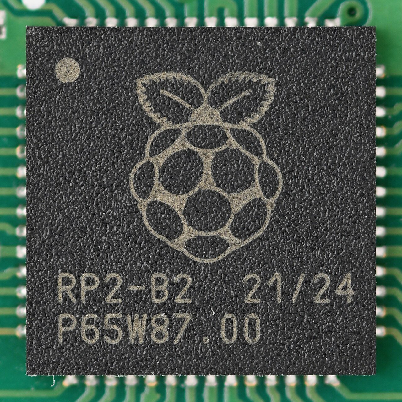
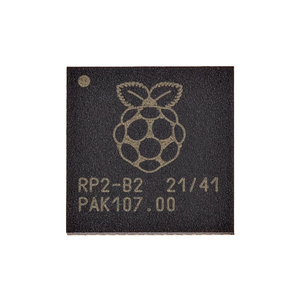
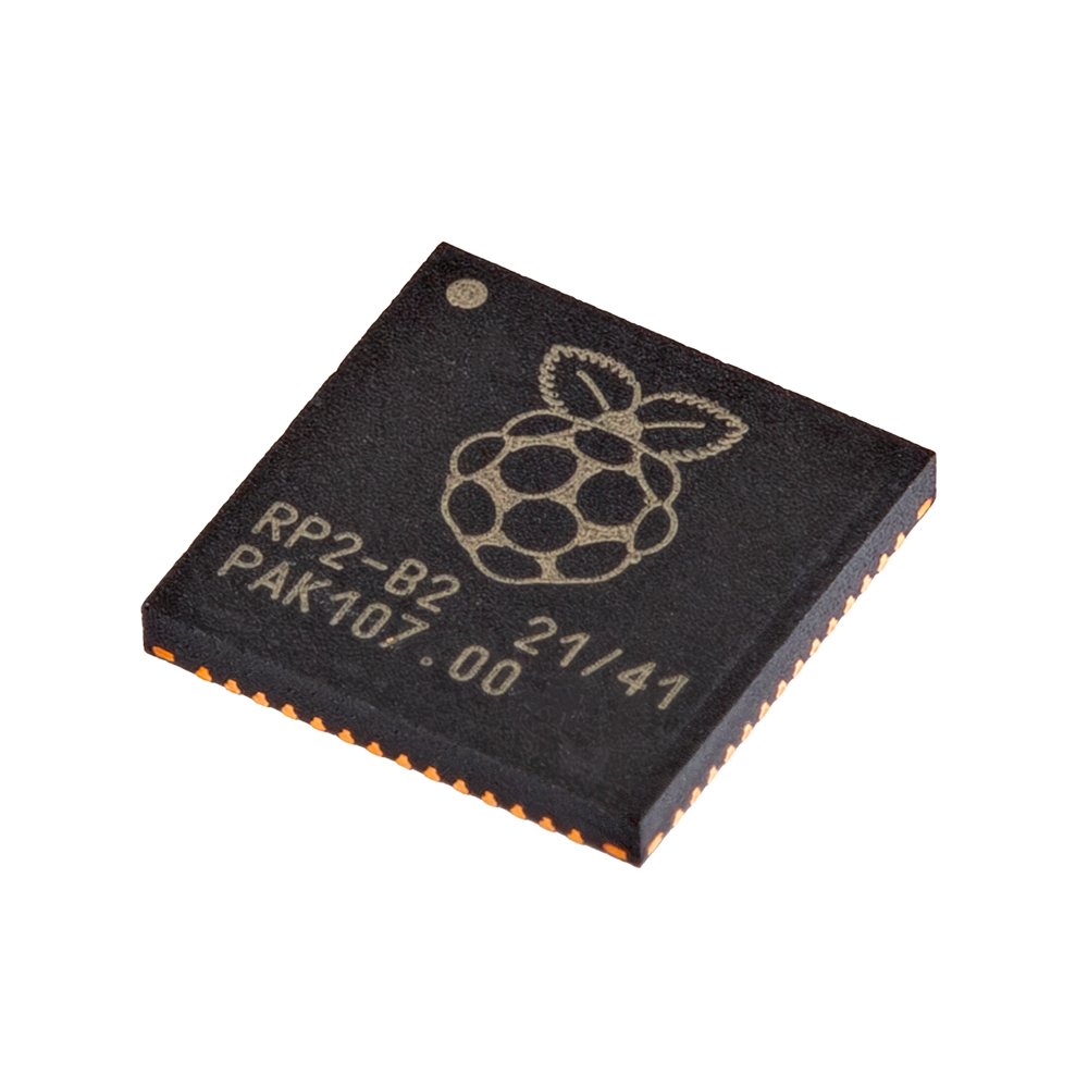
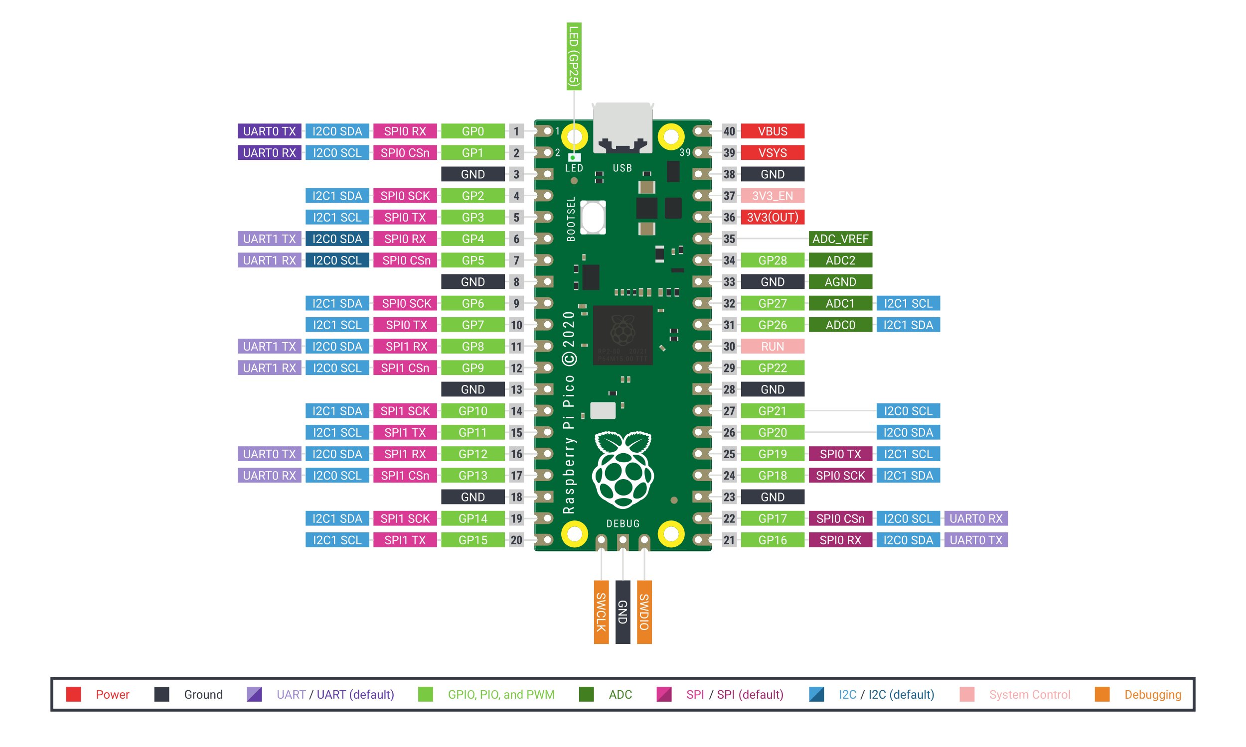
Pinout diagram
| Attr | Specs | verified |
|---|---|---|
cpu | dual ARM Cortex-M0+ (ARMv6-M) @ 133 MHz nominal — datasheet: "Dual Cortex M0+ processor cores, up to 133MHz (or 200MHz at 1.15V, see Section 2.15.3)" (datasheet; also Wikipedia: "Originally run at 133 MHz, but later certified at 200 MHz"). The datasheet documents automatic overclocking using the ROSC (ring oscillator tracks PVT) in §2.15.2.1.5; MicroPython's docs state the core is "overclockable to over 400 MHz" in practice (MicroPython RP2 general info). MicroPython boots at 125 MHz by default and allows machine.freq up to ~250 MHz (MicroPython RP2 quickref). | ✔ |
no_fpu_no_dsp | on Cortex-M0+ — heavy float math is done in software (fast fixed-point/fast-float ROM routines are baked into the RP2040 boot ROM) (Adafruit Feather RP2040 page, SparkFun Pro Micro RP2040 page). | ✔ |
per_core_extras | integer divider + 2 hardware interpolators each (Wikipedia). | ✔ |
gpu | none (bit-banged VGA/DVI is done with PIO — see Features). | ? unverified |
ram | 264 KB SRAM on-chip in six independent banks (four 64 KB + two 4 KB) (Wikipedia, datasheet key features). The 16 KB XIP cache can additionally be used as an extra SRAM bank (errata E9 describes the bootrom caveat). | ✔ |
storage | no internal flash/EEPROM. Dedicated QSPI (SSI) controller with 6 dedicated pins, execute-in-place (XIP) with 16 KB cache, supporting up to 16 MB off-chip flash (datasheet, Wikipedia). Board flash size varies: 2 MB (Pico, Waveshare Zero), 4 MB (Waveshare Plus), 8 MB (Feather/ItsyBitsy/QT Py/Tiny 2040), 16 MB (Pro Micro, Metro, Nano Connect) (vendor pages above, SparkFun, Waveshare). | ✔ |
connectivity | no radio on-chip. *USB 1.1 (LS & FS) controller + PHY, host and device* (1.5/12 Mbit/s) (datasheet key features, Wikipedia). Ethernet/Wi-Fi/BT only via board add-ons (WIZnet W5100S/W5500/W6100 "EVB-Pico" boards, Nano RP2040 Connect, Pico W's CYW43) (Wikipedia board table). | ✔ |
gpio | 30 multifunction GPIO, 4 of which (GP26–GP29) can be analog inputs; 3.3 V logic, not 5 V-tolerant (datasheet, Adafruit). Broken-out count is board-specific: 30 (OLIMEX Pico30), 29 (Waveshare Zero, via pads), 26 (Pico), 21 (Feather), 20 (Pro Micro) (Wikipedia, SparkFun). | ✔ |
fixed_function_peripherals | 2 × UART, 2 × SPI, 2 × I²C, 16 PWM channels (8 slices × 2 channels; 8 Hz–62.5 MHz at 125 MHz clock), 4-channel 12-bit SAR ADC @ 500 ksps (8.7 ENOB) + a 5th muxed channel to the on-chip temperature sensor, 12-channel DMA controller (2 IRQs), timer with 4 alarms, RTC, watchdog, 32 hardware spinlocks (datasheet; PWM slice details and ADC channels per MicroPython RP2 quickref; DMA channel count per Wikipedia — the datasheet's BUS_PRIORITY register exposes 12 DMA write/read priority bits). No DAC, no I²S, no camera, no SDIO — those are PIO territory (Adafruit). | ✔ |
clocking | 12 MHz crystal input (XOSC), 2 PLLs (USB 48 MHz + core), on-chip ring oscillator (ROSC), programmable on-chip LDO for core voltage (datasheet, Adafruit chip features). | ✔ |
power_board_level_varies | Waveshare Zero uses an ME6217C33 LDO (800 mA max); SparkFun Pro Micro an AP2112 3.3 V LDO + PTC fuse; Adafruit Feather a 500 mA-peak 3.3 V regulator plus 200 mA+ LiPo charger (Waveshare, SparkFun, Adafruit). | ✔ |
temperature | RP2040 is qualified to −40 °C minimum operating temperature (changed from −20 °C in the datasheet revision history, Nov 2021 revision) (RP2040 datasheet, revision history). | ✔ |
- Chip manufacturer: Raspberry Pi Ltd (UK) — first microcontroller from "Raspberry Silicon"; announced 21 January 2021 together with the Raspberry Pi Pico (Wikipedia — RP2040). Fabricated by TSMC on a 40 nm process, 7×7 mm QFN-56EP package (Wikipedia, MicroPython RP2 general info).
- Launch price: the RP2040 chip itself launched at US$1 (with the Pico board at US$4) (Wikipedia — RP2040).
- Status: Active (still in full production and still the volume part of the family); its successor is the RP2350 series (2024, Cortex-M33/Hazard3 — see the rp2350-generic card) (Wikipedia — RP2040, MicroPython RP2 general info).
- "Generic board" concept: RP2040 has no internal flash — every board designer picks their own external QSPI flash (2–16 MB), regulator, connector and pinout. This produced an unusually large third-party ecosystem; at launch Adafruit, Pimoroni, Arduino and SparkFun already had designs at an advanced stage (Wikipedia — RP2040).
- Common variants (representative, all sourced): - Adafruit Feather RP2040 — 8 MB flash, 21 GPIO, USB-C, LiPo charger (200 mA+), STEMMA QT I²C connector, NeoPixel, 12 MHz crystal (Adafruit product page). Also ItsyBitsy RP2040 (8 MB, micro-USB), QT Py RP2040 (8 MB), Metro RP2040 (16 MB, SD, DC jack) (Wikipedia board table, Adafruit). - SparkFun Pro Micro RP2040 (DEV-17717) — 16 MB flash, 20 broken-out GPIO, Qwiic connector, WS2812B, USB-C, resettable PTC fuse, AP2112 3.3 V LDO, Pro Micro footprint, 1.3″×0.7″ (SparkFun product page, hardware repo). Also Thing Plus RP2040 (16 MB, LiPo) and MicroMod RP2040 (16 MB, edge connector) (Wikipedia). - Waveshare RP2040-Zero — ultra-cheap Pico-Zero format, 23×18 mm, 2 MB flash (W25Q16JV), USB-C, BOOT+RESET buttons, WS2812 RGB LED, ME6217 LDO (800 mA), 29 GPIO (20 on edge pins, rest on solder pads), castellated for SMD reflow (Waveshare product page). Waveshare also sells RP2040-LCD-0.96 (integrated 0.96″ IPS LCD) and RP2040-Plus (4 MB flash, battery header) (Waveshare selection guide). - Arduino Nano RP2040 Connect — 16 MB flash + ESP32-based NINA module (Wi-Fi/BT), 9-axis IMU, microphone (Wikipedia). - Seeed XIAO RP2040 (20×17.5 mm, 2 MB, USB-C), Pimoroni Tiny 2040 (8 MB) / PicoSystem (16 MB, handheld), WeAct Studio RP2040 (2/4/8/16 MB options), OLIMEX RP2040-PICO30 (all 30 GPIO broken out) (Wikipedia board table). - Price of generic boards: roughly US$3–20 depending on vendor/features.
+ Strengths
- PIO — Programmable I/O (the unique argument): 2 PIO blocks × 4 state machines = 8 user-programmable I/O coprocessors that run custom 32-instruction programs and clock out bit-accurate protocols without any CPU time (datasheet, Adafruit). Real-world PIO implementations in the official examples: VGA, I²S audio, LED matrices (HUB75), NeoPixel/DotStar, software I²C/SPI, IR NEC encode/decode, Manchester encoding, quadrature encoders, one-wire (pico-examples/pio). Adafruit: "create custom hardware logic and data processing blocks that run on their own without taking up a CPU … NeoPixels … I2S audio in or out, LED matrix displays, 8-bit or SPI based TFTs, even VGA" (Adafruit).
- Symmetric dual-core with a fully-connected AHB crossbar, inter-core signalling and 32 hardware spinlocks — unusual architecture at this price point (datasheet, Wikipedia).
- 264 KB RAM — enormous for a $1-class MCU; six banks let DMA/GPIO/proc0/proc1 access proceed without contention (Wikipedia).
- Stateless design: flash is whatever QSPI part you solder on (512 KB → 16 MB), XIP with cache — the reason the generic-board ecosystem exploded (datasheet, SparkFun).
- *USB device and host* on the same 1.1 controller, plus TinyUSB-based Arduino/CircuitPython USB stacks (mouse/keyboard/HID/MIDI/CDC/MSC) (datasheet, arduino-pico README).
- Unbrickable drag-and-drop programming (ROM UF2 bootloader + PICOBOOT) — no external programmer needed for anything (datasheet, microsoft/uf2).
- Certified headroom: 200 MHz operation documented at 1.15 V core, plus a documented ROSC auto-overclocking technique; community/MicroPython report >400 MHz on good silicon (datasheet §2.15.2.1.5, §2.15.3, MicroPython general info).
- Competitive/gaming pedigree: e.g. PhobGCC, the popular open-source Hall-effect GameCube controller motherboard (used in competitive Smash Bros. Melee), is built on the RP2040 (Wikipedia — RP2040, PhobGCC hardware repo).
− Weaknesses
- Silicon errata (RP2040 datasheet, Appendix B) — verified entries in the extracted datasheet text (datasheet): - E9: ROM UF2 bootloader cannot boot directly into XIP cache-as-SRAM (the 16 KB cache-as-extra-RAM trick needs a workaround from SRAM). - E14: sparse or mis-aligned flash-binary UF2 may not be written to flash correctly by the UF2 bootloader — affects hand-built UF2 images. - E12 / E13 (DMA): reading DMA WRITE_ADDR/READ_ADDR mid-sequence gives wrong values; after aborting a channel, ABORT status clears prematurely and a spurious interrupt may fire. - E7: ROSC/XOSC COUNT registers unreliable (do not use for µs delays). - USB device controller: "two hardware issues … with software workarounds on RP2040B0, RP2040B1, and fixed in hardware on RP2040B2" (silicon stepping matters — B2 is the current common one) (§4.1.2.8.5).
- Clock-mux glitch hazard: the clock generators' auxiliary mux "will glitch when changing the select control"; clk_sys/clk_ref have an extra glitchless mux that must be driven with the documented switching sequence, otherwise a peripheral can get a glitchy clock (datasheet, clocks chapter).
- No FPU / no DSP: Cortex-M0+ does floating point in software; heavy float workloads are much slower than on an M4 (use the ROM's accelerated float routines or fixed point) (Adafruit).
- ADC real resolution: 12-bit nominal but 8.7 ENOB, referenced to the (board-noise-sensitive) supply — plan for ~9 usable bits (datasheet ADC chapter).
- XIP stall during flash writes: code executes from the same QSPI flash that firmware updates target; erasing/programming stalls instruction fetches (multicore/interrupt code must be written for this — the SDK provides pico_flash/flash_safe_execute helpers).
- 3.3 V only, no 5 V tolerance on any GPIO — level-shift everything 5 V (Adafruit).
- Generic-board traps: - Pin count ≠ chip GPIO: Waveshare Zero exposes 29 of the chip's GPIOs but only 20 on the edge pinout — the rest only on solder points (Waveshare); SparkFun Pro Micro breaks out just 20 GPIO / 10 PWM channels (SparkFun). - BOOTSEL reuse: on the Adafruit Feather RP2040 the boot button is also wired to GPIO4 so it doubles as a user button — a pin you may not get back cleanly (Adafruit revision history). - Cheap LDOs: Zero-class boards use small LDOs (ME6217, 800 mA) with no SMPS — no Pico-style 1.8–5.5 V VSYS buck-boost; battery voltage range and 3V3 headroom are what the regulator gives you (Waveshare). - Board-definition drift: very obscure clones may lack a PICO_BOARD= definition, a CircuitPython build or a MicroPython uf2 variant; check the SDK boards directory, CircuitPython downloads and the arduino-pico board list before buying (pico-sdk README).
- Retour d'expérience expert expert — expert-microcontroleur
- Bonjour a tous. Je reviens sur la carte rp2040-generic. Les PIO sont effectivement revolutionnaires pour le bit-banging sans toucher au CPU, c'est le vrai point fort. Mais attention aux pieges documentes. L'errata E9 empeche le boot direct en cache-as-SRAM via l'UF2, il faut un workaround depuis la… — expert-microcontroleur
- Salut expert, merci pour ce retour clair. Je debutte avec la SparkFun Pro Micro RP2040. Tu mentionnes la sensibilite au bruit pour l'ADC. Je compte lire un potentiomètre simple pour un controle de volume. Est-ce que les 9 bits suffisent ou dois-je absolument filtrer ? Par ailleurs, j'ai vu des disc… — maker-debutant-42
- @maker-debutant-42 pour ton potar, 9 bits c'est correct pour un volume, mais si tu as un bruit de fond sur ta ligne 3.3V, ca sautera. Le glitch de clock est reel : le datasheet dit que le mux auxiliaire peut creer des glitches si tu ne suis pas la sequence officielle. Si tu utilises MicroPython, ev… — pio-hacker
Community feedback and projects
- Powering an RP2040-lcd-1.28 with 5V via battery connector? forum.arduino.cc
- Issues with I2C Communication on Waveshare RP2040-Zero forum.arduino.cc
- Rust RP2040 `entry` differences stackoverflow.com
- I like the RP2040 dgroshev.com
- RP2040 Doom kilograham.github.io
Content not available yet.
- RP2040 datasheet (official, 642 p., incl. PIO instruction set + Appendix B errata)
- pico-sdk README
- Getting Started with Pico-series / C SDK books
- Getting Started with Pico-series / C SDK books
- Pico SDK
- Pico SDK
- general info
- repo
- MicroPython RP2 port
- CircuitPython
- CircuitPython
- Adafruit guide
- Arduino core (community)
- Rust
- Rust
- Adafruit Feather RP2040
- Adafruit ItsyBitsy RP2040
- SparkFun Pro Micro RP2040
- hardware repo
- Waveshare RP2040-Zero
- Wikipedia RP2040 board table
- Raspberry Pi Pico forums
- rp-rs Matrix chat
- Silicon errata (RP2040 datasheet, Appendix B) — verified entries in the extracted datasheet text (datasheet): - E9: ROM UF2 bootloader cannot boot directly into XIP cache-as-SRAM (the 16 KB cache-as-extra-RAM trick needs a workaround from SRAM). - E14: sparse or mis-aligned flash-binary UF2 may not be written to flash correctly by the UF2 bootloader — affects hand-built UF2 images. - E12 / E13 (DMA): reading DMA WRITE_ADDR/READ_ADDR mid-sequence gives wrong values; after aborting a channel, ABORT status clears prematurely and a spurious interrupt may fire. - E7: ROSC/XOSC COUNT registers unreliable (do not use for µs delays). - USB device controller: "two hardware issues … with software workarounds on RP2040B0, RP2040B1, and fixed in hardware on RP2040B2" (silicon stepping matters — B2 is the current common one) (§4.1.2.8.5).
- Clock-mux glitch hazard: the clock generators' auxiliary mux "will glitch when changing the select control"; clk_sys/clk_ref have an extra glitchless mux that must be driven with the documented switching sequence, otherwise a peripheral can get a glitchy clock (datasheet, clocks chapter).
- No FPU / no DSP: Cortex-M0+ does floating point in software; heavy float workloads are much slower than on an M4 (use the ROM's accelerated float routines or fixed point) (Adafruit).
- ADC real resolution: 12-bit nominal but 8.7 ENOB, referenced to the (board-noise-sensitive) supply — plan for ~9 usable bits (datasheet ADC chapter).
- XIP stall during flash writes: code executes from the same QSPI flash that firmware updates target; erasing/programming stalls instruction fetches (multicore/interrupt code must be written for this — the SDK provides pico_flash/flash_safe_execute helpers).
- 3.3 V only, no 5 V tolerance on any GPIO — level-shift everything 5 V (Adafruit).
- Generic-board traps: - Pin count ≠ chip GPIO: Waveshare Zero exposes 29 of the chip's GPIOs but only 20 on the edge pinout — the rest only on solder points (Waveshare); SparkFun Pro Micro breaks out just 20 GPIO / 10 PWM channels (SparkFun). - BOOTSEL reuse: on the Adafruit Feather RP2040 the boot button is also wired to GPIO4 so it doubles as a user button — a pin you may not get back cleanly (Adafruit revision history). - Cheap LDOs: Zero-class boards use small LDOs (ME6217, 800 mA) with no SMPS — no Pico-style 1.8–5.5 V VSYS buck-boost; battery voltage range and 3V3 headroom are what the regulator gives you (Waveshare). - Board-definition drift: very obscure clones may lack a PICO_BOARD= definition, a CircuitPython build or a MicroPython uf2 variant; check the SDK boards directory, CircuitPython downloads and the arduino-pico board list before buying (pico-sdk README).
- Piloter la LED RGB embarquée WS2812 d'une carte RP2040 générique debutant Schéma : IMG-rp2040-generic-debutant-1-rp2040-neopixel-ws2812.svg — carte RP2040 générique type Waveshare Zero avec sa LED WS2812 sur GP16 mise en évidence, câble USB-C branché, puce PIO représentée générant le signal
- Avoir une console série sur une carte sans pont USB (UART0) debutant Schéma : IMG-rp2040-generic-debutant-2-rp2040-console-serie-uart.svg — carte RP2040 générique reliée à un adaptateur USB-TTL : GP0 TX vers RX de l'adaptateur, GP1 RX vers TX, masses communes, terminal série à 115200 bauds
- Jouer une mélodie avec un buzzer passif et le PWM debutant Schéma : IMG-rp2040-generic-debutant-3-rp2040-buzzer-pwm-melodie.svg — buzzer passif relié à GP8 et GND d'une carte RP2040 générique, forme d'onde carrée 440 Hz annotée, portée avec les notes
- Afficher sur un OLED I2C SSD1306 et déboguer le bus intermediaire Schéma : IMG-rp2040-generic-intermediaire-1-rp2040-i2c-oled-ssd1306.svg — module OLED 0,96 pouces SSD1306 relié en I2C à une carte RP2040 générique : VCC 3V3, GND, SDA sur GP4, SCL sur GP5, écran affichant température et texte
- Logger sur carte microSD en SPI (mode carte) intermediaire Schéma : IMG-rp2040-generic-intermediaire-2-rp2040-sdcard-spi.svg — module lecteur microSD relié en SPI à une carte RP2040 générique : GP2 CS, GP3 MOSI, GP4 MISO, GP5 SCK, 3V3 et GND, fichier journal avec horodatages
- Interruptions GPIO et alarmes matérielles avec le Pico SDK intermediaire Schéma : IMG-rp2040-generic-intermediaire-3-rp2040-interruptions-timer.svg — carte RP2040 avec bouton sur GP2, chronogramme front descendant déclenchant l'IRQ IO_BANK0 puis une alarme du timer 50 ms plus tard, LED de réponse
- Transformer la carte en clavier USB HID avec TinyUSB avance Schéma : IMG-rp2040-generic-avance-1-rp2040-usb-hid-clavier.svg — carte RP2040 générique branchée en USB sur un PC, icône clavier virtuel, bouton physique GP2 envoyant la lettre A, descripteur de rapport HID représenté
- Acquisition ADC à haute fréquence avec le DMA sans CPU avance Schéma : IMG-rp2040-generic-avance-2-rp2040-dma-adc.svg — puce RP2040 avec le routeur DMA reliant ADC et SPI à un buffer en SRAM, deux buffers ping-pong, oscilloscope montrant un signal échantillonné, CPU endormi
- Overclocker le RP2040 à 200 MHz (et au-delà) en toute connaissance avance Schéma : IMG-rp2040-generic-avance-3-rp2040-overclock-200mhz.svg — puce RP2040 avec régulateur VREG et boucle ROSC, clock XOSC 12 MHz multiplié vers 200 MHz, jauge de fréquence 133 vers 200 MHz, thermomètre de la puce
Code library — examples written for this board
clignotante.pyPythonbouton-interruption.pyPythonpwm-servo.pyPythonlecture-adc.pyPythonneopixel.pyPythonoled-i2c.pyPythoncapteur-dht.pyPythonjournalisation.pyPythonuart-commandes.pyPythontaches-cooperatives.pyPython
Examples and repos found online
- raspberrypi/pico-examples github.com
- raspberrypi/pico-sdk github.com
- micropython/micropython github.com
- earlephilhower/arduino-pico github.com