Raspberry Pi Compute Module 1 (CM1)
⚡ The essentials in 60 seconds
- soc — Broadcom BCM2835 — single-core ARM1176JZF-S (ARMv6, ARM11 family) at 700 MHz, with VideoCore IV GPU (documentation mirror, compute-module introduction; RP-008161-DS datasheet, retrieved 2026-10-13). The datasheet confirms CM1 uses the same BCM2835 as the original Raspberry Pi Model B/B+ and lists the software ISA as ARMv6.
- ram — 512 MB LPDDR2, shared between CPU and GPU (GPU/CPU split configured via gpu_mem in config.txt) (RP-008161-DS, retrieved 2026-10-13).
- storage — 4 GB eMMC soldered on-module, wired directly to the BCM2835's primary SD/eMMC interface (not broken out to the connector); eMMC I/O voltage is fixed at 1.8 V (RP-008161-DS, retrieved 2026-10-13).
- connectivity — No Wi-Fi, no Bluetooth, no Ethernet on the module. One USB 2.0 host/OTG port (shared: the module has a single USB interface), HDMI 1.3a (via TMDS pins + CEC/DDC), composite video out (TVDAC pin), HDMI CEC. The CMIO v1/v3 IO Boards expose HDMI, one USB 2.0 Type-A, camera/display FPC connectors — still no Ethernet (RP-008161-DS; compute-module introduction, retrieved 2026-10-13).
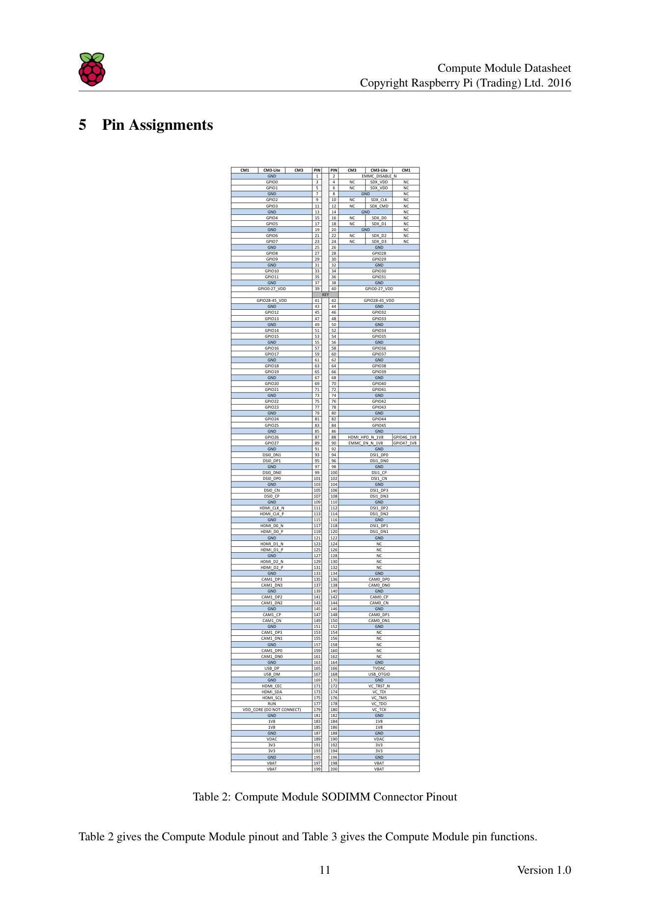
- gpio_peripherals_from_the_datasheet_s_peripheral_list — 48× GPIO lines total (BCM283x has 54 GPIOs in 3 voltage banks; bank 2 is used internally for the eMMC, GPIO0–27 = bank 0, GPIO28–45 = bank 1, GPIO46/47 are 1.8 V special functions HDMI_HPD_N / EMMC_EN_N); 2× I2C, 2× SPI, 2× UART, PCM/I2S, 2× hardware PWM (PWM0/1), 3× GPCLK, 2× SD/SDIO, JTAG, DPI (24-bit parallel RGB display), SMI (NAND/SRAM "Secondary Memory Interface"), 4-lane + 2-lane MIPI CSI camera and 4-lane + 2-lane MIPI DSI display interfaces (each up to 1 Gbps/lane) (RP-008161-DS, retrieved 2026-10-13). No ADC; the only analog output is the composite TV DAC. GPIO bank supply (VDD_IO) is externally selectable at 1.8 V / 2.7 V / 3.3 V per bank; per-GPIO drive up to 16 mA, ≤50 mA aggregate per bank.
- form_factor — DDR2-SODIMM mechanically-compatible System-on-Module, 200-pin connector, JEDEC MO-224 (1.8 V SODIMM outline), 30 mm module height, ~68×30 mm board area as reported at announcement; electrically NOT compatible with DDR2 SODIMM sockets (RP-008161-DS; Wired UK, retrieved 2026-10-13).
- On this board : 9 tutorials · 10 code
The Raspberry Pi Compute Module 1, announced in April 2014, represents a pivotal moment in the history of single-board computing, marking the Raspberry Pi Foundation’s strategic entry into the industrial and embedded markets. While the original Raspberry Pi Model B was designed as a standalone educational computer with accessible ports, the Compute Module 1 was conceived as a component rather than a finished product. It is a System-on-Module, meaning it integrates the core computing elements—the processor, memory, and storage—onto a single compact circuit board that is intended to be plugged into a custom carrier board. This design philosophy allows manufacturers to create sleek, compact devices without the bulk of standard ports like USB or Ethernet, which are instead provided by the custom carrier. At its launch, the module was priced at approximately thirty US dollars for bulk orders, making it an attractive option for developers seeking to integrate Linux-based computing into commercial products. However, it is important to note that this specific model is now considered legacy hardware. It was officially moved to legacy status in January 2019, with an end-of-life guarantee extending only until January 2026, signaling that new designs should look toward newer generations like the Compute Module 4 or 5.
At the heart of the Compute Module 1 is the Broadcom BCM2835 system-on-chip, the same processor found in the original Raspberry Pi Model B. This chip features a single-core ARM1176JZF-S processor running at 700 MHz, based on the ARMv6 instruction set. For those unfamiliar with these terms, the ARMv6 architecture is an older standard that limits the software compatibility of the device compared to modern smartphones or computers. The processor is paired with 512 MB of LPDDR2 RAM, which is shared between the central processing unit and the VideoCore IV graphics processing unit. This shared memory architecture means that the amount of memory available for running applications depends on how much is allocated to graphics rendering, a configuration adjustable via software settings. Storage is provided by 4 GB of eMMC flash memory soldered directly onto the module. Unlike the original Raspberry Pi, which used removable SD cards, the Compute Module 1 has no SD card slot. This fixed storage enhances reliability for industrial applications where removable media might be a point of failure or security risk, but it also means that updating the operating system requires a specific procedure involving a host computer.
The physical form factor of the Compute Module 1 is a 200-pin connector that mechanically resembles a DDR2 SODIMM, a type of memory module used in older laptops. However, it is crucial to understand that while it fits physically into similar slots, it is not electrically compatible with standard laptop memory. The module measures approximately 68 by 30 millimeters and is designed to be soldered or plugged into a custom carrier board. This connector exposes a vast array of input and output options, far exceeding what is available on the standard Raspberry Pi. These include forty-eight general-purpose input/output lines, two I2C interfaces for connecting sensors, two SPI interfaces for high-speed peripherals, and two UART serial ports. It also supports advanced display and camera interfaces, including MIPI CSI for cameras and MIPI DSI for displays, allowing for high-bandwidth connections that are not possible with the older HDMI or composite video outputs alone. The GPIO pins are organized into voltage banks, with the ability to select the operating voltage for each bank at 1.8, 2.7, or 3.3 volts, providing flexibility for interfacing with a wide variety of electronic components.
Connectivity on the module itself is minimal by design. The Compute Module 1 does not include Wi-Fi, Bluetooth, or Ethernet. Instead, it provides a single USB 2.0 interface that can operate in host or on-the-go mode, along with HDMI and composite video outputs. To add network connectivity or additional USB ports, developers must design these features into their custom carrier board. The official reference design, known as the Compute Module IO Board, demonstrates this approach by providing HDMI, USB, and camera connectors, but even this board lacks Ethernet, requiring an external adapter for wired networking. This modular approach ensures that the core computing engine remains compact and power-efficient, while allowing for extreme customization of the peripheral interfaces based on the specific needs of the end product.
Powering the Compute Module 1 requires careful attention to detail, as it operates on multiple voltage rails supplied by the carrier board. Unlike later models that accept a simple 5-volt input, the CM1 requires separate 3.3-volt, 1.8-volt, and battery backup rails. The power supply must ramp up in a specific descending voltage order to prevent damage to the internal circuits, a phenomenon known as latch-up. This requirement makes the power chain design critical for stable operation, and the datasheet explicitly warns that improper sequencing can lead to unreliable behavior or hardware failure. The module is rated for operation between minus twenty-five and plus eighty degrees Celsius, making it suitable for a range of industrial environments, though thermal management is still necessary to prevent the processor from throttling its speed when internal temperatures exceed eighty-five degrees.
Software support for the Compute Module 1 is tied to its older ARMv6 architecture. The most compatible operating system is the 32-bit version of Raspberry Pi OS, specifically the Bullseye release or earlier. Newer versions of the operating system, such as Bookworm, target newer instruction sets and may not boot correctly on this hardware. Installing the operating system is a unique process because there is no SD card slot. Developers must use a tool called rpiboot, which puts the module into a USB slave mode, allowing it to be recognized as a mass storage device by a host computer. Once connected, the internal eMMC can be flashed with an operating system image using standard tools like Raspberry Pi Imager or the command-line utility dd. This process is well-documented but requires a specific hardware setup, typically involving the official IO Board and a jumper setting to enable USB boot mode.
Despite its age, the Compute Module 1 remains a significant piece of hardware history, having powered commercial products like the Slice media player and various industrial controllers. Its legacy lies in proving that a Linux-based computer could be embedded into products at a low cost and small form factor. However, potential users should be aware of its limitations. The lack of a secure boot mechanism means that security relies entirely on the software layer, lacking the hardware-backed key storage found in newer modules. Additionally, the camera and display interfaces are closed, meaning they only work with specific sensors and displays supported by the official firmware. For new projects, the Raspberry Pi Foundation recommends migrating to the Compute Module 4 or 5, which offer better performance, modern security features, and active support. Nevertheless, for maintenance of existing systems or educational purposes, the Compute Module 1 serves as a foundational example of modular embedded computing, demonstrating the trade-offs between flexibility, cost, and complexity in hardware design.
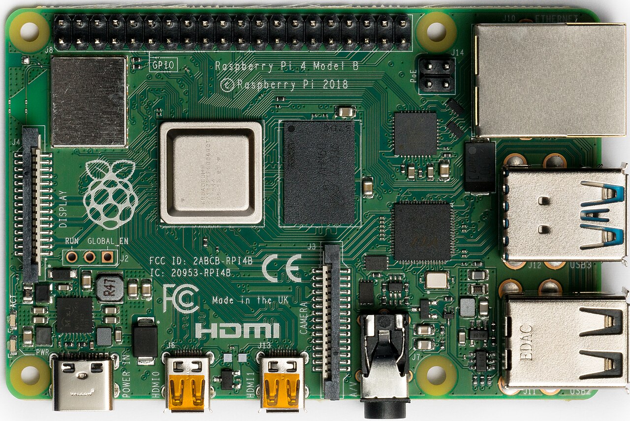
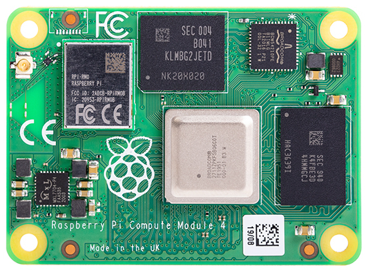
Pinout diagram
| Attr | Specs | verified |
|---|---|---|
soc | Broadcom BCM2835 — single-core ARM1176JZF-S (ARMv6, ARM11 family) at 700 MHz, with VideoCore IV GPU (documentation mirror, compute-module introduction; RP-008161-DS datasheet, retrieved 2026-10-13). The datasheet confirms CM1 uses the same BCM2835 as the original Raspberry Pi Model B/B+ and lists the software ISA as ARMv6. | ✔ |
ram | 512 MB LPDDR2, shared between CPU and GPU (GPU/CPU split configured via gpu_mem in config.txt) (RP-008161-DS, retrieved 2026-10-13). | ✔ |
storage | 4 GB eMMC soldered on-module, wired directly to the BCM2835's primary SD/eMMC interface (not broken out to the connector); eMMC I/O voltage is fixed at 1.8 V (RP-008161-DS, retrieved 2026-10-13). | ✔ |
connectivity | No Wi-Fi, no Bluetooth, no Ethernet on the module. One USB 2.0 host/OTG port (shared: the module has a single USB interface), HDMI 1.3a (via TMDS pins + CEC/DDC), composite video out (TVDAC pin), HDMI CEC. The CMIO v1/v3 IO Boards expose HDMI, one USB 2.0 Type-A, camera/display FPC connectors — still no Ethernet (RP-008161-DS; compute-module introduction, retrieved 2026-10-13). | ✔ |
gpio_peripherals_from_the_datasheet_s_peripheral_list | 48× GPIO lines total (BCM283x has 54 GPIOs in 3 voltage banks; bank 2 is used internally for the eMMC, GPIO0–27 = bank 0, GPIO28–45 = bank 1, GPIO46/47 are 1.8 V special functions HDMI_HPD_N / EMMC_EN_N); 2× I2C, 2× SPI, 2× UART, PCM/I2S, 2× hardware PWM (PWM0/1), 3× GPCLK, 2× SD/SDIO, JTAG, DPI (24-bit parallel RGB display), SMI (NAND/SRAM "Secondary Memory Interface"), 4-lane + 2-lane MIPI CSI camera and 4-lane + 2-lane MIPI DSI display interfaces (each up to 1 Gbps/lane) (RP-008161-DS, retrieved 2026-10-13). No ADC; the only analog output is the composite TV DAC. GPIO bank supply (VDD_IO) is externally selectable at 1.8 V / 2.7 V / 3.3 V per bank; per-GPIO drive up to 16 mA, ≤50 mA aggregate per bank. | ✔ |
form_factor | DDR2-SODIMM mechanically-compatible System-on-Module, 200-pin connector, JEDEC MO-224 (1.8 V SODIMM outline), 30 mm module height, ~68×30 mm board area as reported at announcement; electrically NOT compatible with DDR2 SODIMM sockets (RP-008161-DS; Wired UK, retrieved 2026-10-13). | ✔ |
power | Powered from the carrier at 3.3 V rails (unlike CM4/CM5 which take 5 V): minimum recommended supplies are VBAT ≥ 2000 mW, 3V3 ≥ 250 mA, 1V8 ≥ 250 mA, VDAC ≥ 25 mA (clean 2.5–2.8 V, LDO from 3V3 recommended for composite out); supplies must ramp in descending voltage order (or simultaneously) to avoid latch-up (RP-008161-DS §7, retrieved 2026-10-13). The official IO Board accepts 5 V via GPIO header or micro USB and generates the 3.3 V rails (compute-module introduction). | ✔ |
temperature | The narrowest-rated components (eMMC, LPDDR2) are rated −25 °C to +80 °C; the datasheet states this as the nominal module range for CM3/CM3L built from the same memory/eMMC classes. Treat −25…+80 °C as the practical CM1 envelope, with thermal design headroom required (RP-008161-DS §10, retrieved 2026-10-13). | ✔ |
- Manufacturer: Raspberry Pi (Trading) Ltd / Raspberry Pi Foundation (Cambridge, UK).
- Year: Announced 7 April 2014 (Wired UK, "Raspberry Pi announces customisable module for industry", retrieved 2026-10-13); Wikipedia's history section likewise places the Compute Module's appearance in April 2014 (Wikipedia, Raspberry Pi — "Product line expansion (2014–present)", retrieved 2026-10-13).
- Launch price: US$30 (≈£18) per module in batches of 100 at announcement; individual retail "slightly higher" (Wired UK, 2026-10-13 retrieval).
- Status: Legacy. The official CM1/CM3 datasheet release history records "CM1/CM3/CM3L move to legacy status (not recommended for new designs)" on 25/01/2019, and release 4 (04/08/2021) set the earliest EOL date to 2026; Raspberry Pi guaranteed availability "until at least January 2026" (CM1/CM3 datasheet RP-008161-DS, retrieved 2026-10-13). The current official docs still describe CM1 as "a supported product with an end-of-life (EOL) date no earlier than January 2026" (documentation mirror, datasheet.adoc, retrieved 2026-10-13).
- Variants: A single hardware configuration — 512 MB RAM + 4 GB eMMC. Unlike CM3 and later, there was no "Lite" (storage-less) CM1 and no RAM/eMMC options (RP-008161-DS; documentation mirror, compute-module introduction, both retrieved 2026-10-13).
+ Strengths
- First Raspberry Pi System-on-Module (2014): the original Pi's SoC/RAM/eMMC in a 200-pin SODIMM-outline module with no connectors, designed to be dropped into custom carrier boards — Raspberry Pi's entry into the industrial/embedded market (Wired UK, 2014; Wikipedia, retrieved 2026-10-13).
- I/O far beyond a Model B: dual MIPI CSI camera interfaces (4-lane + 2-lane), dual MIPI DSI display interfaces, 24-bit parallel DPI display interface, SMI NAND/SRAM bus, composite video out, JTAG, 46 general-purpose GPIOs with per-bank selectable I/O voltage (1.8/2.7/3.3 V) — none of this is available on the equivalent Model B board (RP-008161-DS §2.2, §9, retrieved 2026-10-13).
- Solder-down reliability: eMMC storage and LPDDR2 are on-module; connector pins have 35 µm hard gold plating; long guaranteed availability (industrial lifecycle policy, ≥ January 2026) (RP-008161-DS, retrieved 2026-10-13).
- USB slave boot & field flashing: EMMC_DISABLE_N pin + USB OTG allow booting and reflashing the eMMC from a host PC without any removable media (rpiboot) (RP-008161-DS §8, retrieved 2026-10-13).
- Open reference carrier: the Compute Module IO Board (CMIO v1, 2014; CMIO3 also accepts CM1) is an open-source reference design with published schematics (RP-008256-DS CMIO schematics; compute-module introduction, retrieved 2026-10-13).
- No security engine: no secure boot, no TPM/OTP keystore of the CM4/CM5 era — CM1 security is plain Linux userspace security only (cm-bootloader.adoc — EEPROM/secure-boot features are "since CM4", retrieved 2026-10-13).
− Weaknesses
- USB boot enumeration bug (officially documented): "The CM1 bootloader returns a slightly incorrect USB packet to the host. Most USB hosts ignore it, but some USB ports don't work due to this bug. CM3 fixed this bug." Workaround: try different USB ports/hosts (avoid hubs) (Flash an image to a Compute Module — Known issues, retrieved 2026-10-13).
- Legacy / EOL risk: moved to "legacy, not recommended for new designs" in Jan 2019; guaranteed availability ended January 2026 — new designs should migrate (official white paper: Transition from Compute Module 1 or Compute Module 3 to Compute Module 4, RP-003469-WP) (RP-008161-DS release history, retrieved 2026-10-13).
- Powerchain sensitivity: supplies must come up in descending-voltage order or simultaneously or you risk forward-biasing on-chip diodes / latch-up; VBAT must deliver ≥2 W peaks; VDAC needs a clean 2.5–2.8 V rail for composite out. The datasheet explicitly warns that powerchain design "is critical for stable and reliable operation" (RP-008161-DS §7, §9.6, retrieved 2026-10-13).
- eMMC is fixed at 1.8 V I/O and non-removable; reflashing requires the EMMC_DISABLE_N/EMMC_EN_N MOSFET dance (1.8 V-gate-threshold MOSFETs) as on the IO Board, and after USB boot the module needs a couple of seconds of eMMC retry timeout before falling back to USB boot (RP-008161-DS §8, retrieved 2026-10-13).
- CSI/DSI are closed interfaces: "the CSI interface is not openly documented and only CSI camera sensors supported by the official Raspberry Pi firmware will work" (OmniVision OV5647, Sony IMX219); same for DSI displays — anything else must go over USB (RP-008161-DS §9.2–9.3, retrieved 2026-10-13).
- Thermal throttling: DVFS throttles core voltage/frequency when the die exceeds 85 °C; in sealed metal enclosures the ARM11+VC4 can sustain 100% load but will clock back (RP-008161-DS §10, retrieved 2026-10-13).
- CM1→CM3 retrofit traps: CM3 is 1 mm taller (30→31 mm), draws much more on VBAT, and moved GPIO46/47 (HDMI_HPD_N, EMMC_EN_N) to an IO expander — CM1 carrier designs must check these before dropping in a CM3 (RP-008161-DS §1, retrieved 2026-10-13).
- Community-reported quirks: under-voltage and brown-out behaviour on weak 5 V→3.3 V carrier designs, and single-USB-port bandwidth exhaustion when stacking Ethernet+webcam on the IO Board, are recurring themes in the Raspberry Pi forums' Compute Module section (forums.raspberrypi.com — Compute Module forum, retrieved 2026-10-13).
- Retour d'expérience expert expert — expert-raspberrypi
- Petit retour d'experience sur la CM1, qui est officiellement en statut legacy depuis janvier 2019. Si vous bossez dessus, attention au bug de boot USB documente : le bootloader envoie un paquet incorrect que certaines cartes meres ignorent, mais d'autres bloquent completement. Le seul contournement… — expert-raspberrypi
- Merci pour le rappel sur l'alim, j'ai effectivement eu des coupures bizarres avec mon carrier board maison avant de comprendre que la sequence de montee des rails etait trop rapide. Par contre, je bloque sur le reflash de l'eMMC via USB. Malgre le passage a 1.8V sur EMMC_DISABLE_N, le module ne sem… — maker_bricole
- Oui, le timeout de retry de l'eMMC est normal, il faut patienter environ deux secondes après la mise a la terre de la broche. Attention aussi, si tu comptes migrer vers une CM3 plus tard, verifie bien la hauteur du module (1 mm de plus) et surtout que ton schéma ne repose pas sur les GPIO 46 et 47 … — embed_dev
Community feedback and projects
- Power Supply for EDATEC's Compute Module I/O Boards and 12V Computers forum.digikey.com
- EDATEC의 Compute Module I/O 보드와 12V 컴퓨터용 전원 공급 장치 forum.digikey.com
- Raspberry PI Compute Module - SPI1 stackoverflow.com
- bluetooth connection error between raspberry pi compute module and blend micro stackoverflow.com
- Design Your Own Raspberry Pi Compute Module PCB instructables.com
Content not available yet.
- CM1/CM3 datasheet (official)
- CM1 schematics
- Compute Module IO Board schematics
- Compute Module IO Board schematics
- Compute Module IO Board schematics
- Camera/Display Adapter Board (CMCDA)
- Migration white paper (CM1/CM3 → CM4)
- Official docs (Compute Module page, mirror)
- BCM2835 SoC
- usbboot / rpiboot
- Community
- Community
- Announcement coverage
- USB boot enumeration bug (officially documented): "The CM1 bootloader returns a slightly incorrect USB packet to the host. Most USB hosts ignore it, but some USB ports don't work due to this bug. CM3 fixed this bug." Workaround: try different USB ports/hosts (avoid hubs) (Flash an image to a Compute Module — Known issues, retrieved 2026-10-13).
- Legacy / EOL risk: moved to "legacy, not recommended for new designs" in Jan 2019; guaranteed availability ended January 2026 — new designs should migrate (official white paper: Transition from Compute Module 1 or Compute Module 3 to Compute Module 4, RP-003469-WP) (RP-008161-DS release history, retrieved 2026-10-13).
- Powerchain sensitivity: supplies must come up in descending-voltage order or simultaneously or you risk forward-biasing on-chip diodes / latch-up; VBAT must deliver ≥2 W peaks; VDAC needs a clean 2.5–2.8 V rail for composite out. The datasheet explicitly warns that powerchain design "is critical for stable and reliable operation" (RP-008161-DS §7, §9.6, retrieved 2026-10-13).
- eMMC is fixed at 1.8 V I/O and non-removable; reflashing requires the EMMC_DISABLE_N/EMMC_EN_N MOSFET dance (1.8 V-gate-threshold MOSFETs) as on the IO Board, and after USB boot the module needs a couple of seconds of eMMC retry timeout before falling back to USB boot (RP-008161-DS §8, retrieved 2026-10-13).
- CSI/DSI are closed interfaces: "the CSI interface is not openly documented and only CSI camera sensors supported by the official Raspberry Pi firmware will work" (OmniVision OV5647, Sony IMX219); same for DSI displays — anything else must go over USB (RP-008161-DS §9.2–9.3, retrieved 2026-10-13).
- Thermal throttling: DVFS throttles core voltage/frequency when the die exceeds 85 °C; in sealed metal enclosures the ARM11+VC4 can sustain 100% load but will clock back (RP-008161-DS §10, retrieved 2026-10-13).
- CM1→CM3 retrofit traps: CM3 is 1 mm taller (30→31 mm), draws much more on VBAT, and moved GPIO46/47 (HDMI_HPD_N, EMMC_EN_N) to an IO expander — CM1 carrier designs must check these before dropping in a CM3 (RP-008161-DS §1, retrieved 2026-10-13).
- Community-reported quirks: under-voltage and brown-out behaviour on weak 5 V→3.3 V carrier designs, and single-USB-port bandwidth exhaustion when stacking Ethernet+webcam on the IO Board, are recurring themes in the Raspberry Pi forums' Compute Module section (forums.raspberrypi.com — Compute Module forum, retrieved 2026-10-13).
- Flasher l'eMMC du CM1 avec rpiboot et le jumper J4 debutant Schéma : IMG-cm1-debutant-1-flasher-emmc-rpiboot-j4.svg — Le Compute Module 1 relié au PC par USB, le jumper J4 positionné sur 1-2, la puce eMMC apparaissant comme disque USB de masse pour la commande dd
- Premier boot : Bullseye legacy, rails 3,3 V et ordre des alimentations debutant Schéma : IMG-cm1-debutant-2-premier-boot-bullseye.svg — Le Compute Module 1 sur son IO Board alimenté en 3,3 V, avec un avertissement Bookworm barré (ARMv6 non supporté) et un chronogramme montrant la rampe d'alimentation en ordre décroissant
- Première LED sur GPIO17 : banques, courants et broches réservées debutant Schéma : IMG-cm1-debutant-3-led-gpio17-cm1.svg — Le connecteur du Compute Module 1 avec la banque 0 (broches 0-27) et la banque 1 (28-45), les broches réservées GPIO46/47 barrées, et une LED avec résistance sur GPIO17
- Servo moteur sur PWM0 (GPIO18) : 50 Hz et 2,5 à 12,5 % intermediaire Schéma : IMG-cm1-intermediaire-1-servo-pwm-gpio18.svg — Un servo moteur branché sur GPIO18 du Compute Module 1, avec le chronogramme PWM 50 Hz annoté des impulsions 0,5 ms à 2,5 ms correspondant à 2,5 % à 12,5 % de rapport cyclique
- BME280 sur I2C0 (GPIO2/3) : activer i2c_arm et lire l'ID 0x60 intermediaire Schéma : IMG-cm1-intermediaire-2-bme280-i2c0-cm1.svg — Un capteur BME280 adresse 0x76 relié aux broches GPIO2 (SDA) et GPIO3 (SCL) du Compute Module 1, avec la ligne dtparam=i2c_arm=on dans config.txt et le registre 0xD0 renvoyant 0x60
- Caméra officielle sur le connecteur FPC CSI du CM1 intermediaire Schéma : IMG-cm1-intermediaire-3-camera-ov5647-fpc.svg — Un module caméra v2 OV5647 relié par nappe FPC au connecteur CSI fermé du Compute Module 1, avec la mention des capteurs acceptés OV5647 et IMX219 uniquement et la ligne start_x=1 dans config.txt
- Boot sans EEPROM : fallback USB et bootcode.bin sur eMMC avance Schéma : IMG-cm1-avance-1-boot-sans-eeprom-fallback-usb.svg — La séquence de boot du Compute Module 1 sans EEPROM : tentative eMMC avec timeout d'environ 2 secondes, repli sur le mode périphérique USB, et la partition FAT de l'eMMC contenant bootcode.bin et config.txt
- Chaîne d'alimentation VDD_IO : tension par banque, eMMC en 1,8 V et rampe avance Schéma : IMG-cm1-avance-2-vdd-io-powerchain.svg — Les trois tensions possibles de VDD_IO (1,8 V, 2,7 V, 3,3 V) appliquées par banque de GPIO du Compute Module 1, l'eMMC fixée en 1,8 V, l'entrée VBAT consommant au moins 2 W, et la rampe d'alimentation en ordre décroissant
- Provisionnement en masse de l'eMMC et migration CM1 vers CM4 avance Schéma : IMG-cm1-avance-3-provisionnement-emmc-migration-cm4.svg — Une station de provisioning écrivant la même image sur une rangée de Compute Modules via dd, avec le document white paper RP-003469-WP en référence et le gabarit de hauteur passant de 30 à 31 mm pour la migration CM1 vers CM4
Code library — examples written for this board
clignotante.pyPythonbouton-gpio.pyPythoncapteur-i2c.shBashsurveillance-temperature.shBashcapteur-dht11.pyPythonservo-pwm-sysfs.shBashserveur-web-capteur.pyPythonreseau-ethernet.shBashjournal-cron.shBashveilleur-systemd.pyPython
Examples and repos found online
- raspberrypi/usbboot github.com
- raspberrypi/noobs github.com
- raspberrypi/userland github.com
- WiringPi/WiringPi github.com