ESP32-S2
⚡ The essentials in 60 seconds
- cpu — single-core Tensilica Xtensa LX7 @ up to 240 MHz (160 MHz default in many configs); no GPU ( ESP32-S2 datasheet URL above).
- memory — 320 KB internal SRAM, ~1.5 KB low-power SRAM, 448 KB ROM; external SPI flash up to 16 MB (4/8 MB typical); optional quad PSRAM (module-dependent) (ESP32-S2 datasheet:
- connectivity — Wi-Fi 802.11 b/g/n 2.4 GHz (HT40, ESP-WIFI-MESH). No Bluetooth at all — a defining cut vs the ESP32 (
- usb — native USB-OTG (device + host) on GPIO19 (D−)/GPIO20 (D+) — flash/debug over USB without any bridge chip; basis of the QT-Py form factor (
- gpio — 43 programmable GPIOs, freely matrix-routed to USB-OTG, LCD (8080/SPI), 8-bit parallel camera interface, SPI, I2S, UART, ADC, DAC, touch (14 capacitive-touch GPIOs) ( - ADC: 12-bit SAR, up to 20 channels (ADC1 GPIO1–14 + ADC2); ADC2 blocked while Wi-Fi runs (datasheet URL above). - DAC: one 8-bit channel (GPIO17) (datasheet URL above). - LEDC PWM, RMT, motor-control PWM, SDIO master (datasheet URL above).
- logic_level — 3.3 v
- On this board : 9 tutorials · 10 code
The ESP32-S2, developed by Espressif Systems, represents a distinct evolution within the popular ESP32 family of microcontrollers. Announced in 2019 and entering volume production in 2020, this chip is notable for being the first member of the family to operate exclusively on Wi-Fi, deliberately omitting Bluetooth connectivity. This design choice allows Espressif to focus on specific use cases where wireless networking is paramount, while significantly enhancing other features such as security and native USB support. The chip is built around a single-core Tensilica Xtensa LX7 processor, which runs at speeds up to 240 MHz, though it often defaults to 160 MHz in many configurations to balance performance with power consumption. Unlike some other microcontrollers that rely on external chips for USB communication, the ESP32-S2 features native USB-OTG (On-The-Go) functionality. This means it can act as both a USB device and a USB host directly through its GPIO pins, specifically GPIO19 and GPIO20. This capability eliminates the need for a separate USB-to-serial bridge chip, allowing developers to flash code and debug directly over a standard USB connection, a feature that has become foundational for compact board designs like the Adafruit QT Py.
In terms of memory and storage, the ESP32-S2 integrates 320 KB of internal SRAM and 448 KB of ROM, providing ample space for running complex applications without immediate reliance on external memory. It supports external SPI flash memory up to 16 MB, with 4 MB or 8 MB being typical configurations for most development boards. Some variants also offer optional quad PSRAM (Pseudo-Static RAM), which provides faster access speeds than standard flash, although it is important to note that using external PSRAM can conflict with Wi-Fi operations on this specific chip. When the Wi-Fi radio is active, access to external PSRAM is restricted, requiring developers to carefully manage memory allocation to ensure critical data remains in the faster internal SRAM. The connectivity suite is centered on Wi-Fi 802.11 b/g/n operating at 2.4 GHz, supporting features like ESP-WIFI-MESH for creating self-healing networks. However, the complete absence of Bluetooth is a defining characteristic that developers must consider; applications that previously relied on Bluetooth Low Energy (BLE) for device provisioning or pairing will need to adapt by using Wi-Fi SoftAP or USB-based provisioning methods instead.
The input and output capabilities of the ESP32-S2 are robust, featuring 43 programmable GPIOs that can be flexibly routed to various peripherals through an internal matrix. This flexibility supports a wide range of interfaces, including SPI, I2S, UART, and an 8-bit parallel camera interface, making the chip suitable for human-machine interface (HMI) applications and camera-based projects without the overhead of a dual-core processor. Additionally, the chip includes 14 capacitive touch channels, allowing for the creation of touch-sensitive controls without the need for dedicated touch controller chips. The analog capabilities include a 12-bit SAR ADC with up to 20 channels and a single 8-bit DAC channel. A critical technical detail for developers is that the ADC2 peripheral is unavailable while the Wi-Fi radio is active, a limitation shared with the original ESP32, so analog sensors must be connected to ADC1 channels if the device is constantly connected to a network. The logic level for all GPIOs is 3.3 V, and the pins are not tolerant to 5 V signals, requiring level shifters when interfacing with older 5 V electronics.
Security is a major pillar of the ESP32-S2’s design, positioning it as a flagship for secure IoT applications in its generation. It features hardware-accelerated security blocks that support RSA-3072 secure boot, which ensures that only signed and trusted firmware can run on the device. It also includes AES-128, 192, and 256-XTS flash encryption to protect stored data, along with protected key storage and anti-fault-injection hardening to guard against physical attacks. These features make it an attractive choice for products where data integrity and device authenticity are critical. The chip operates within a temperature range of -40 °C to +105 °C, making it suitable for industrial and outdoor environments. Power efficiency is another strength, with deep sleep modes consuming single-digit microamperes, allowing for battery-powered devices that can wake up via real-time clock (RTC) timers or external events.
Development for the ESP32-S2 is well-supported through the official ESP-IDF framework, which targets the esp32s2 architecture, as well as through popular platforms like Arduino, MicroPython, and CircuitPython. The Arduino core supports USB-CDC and TinyUSB HID, enabling the creation of custom USB keyboards, mice, or MIDI devices without additional hardware. However, developers should be aware of certain hardware quirks. For instance, specific strapping pins like GPIO0, GPIO45, and GPIO46 control boot modes and voltage settings; incorrectly loading these pins at power-on can prevent the chip from booting. Furthermore, on certain module variants like the S2R8, pins GPIO33 through GPIO37 may be internally connected to the flash or PSRAM memory, rendering them unavailable for general use. It is also worth noting that the development kit landscape has seen some consolidation, with the older ESP32-S2-DevKitM-1 being discontinued in favor of the ESP32-S2-DevKitC-1, although documentation for the older kit may still be found online. Despite these considerations, the ESP32-S2 remains a versatile and powerful option for projects requiring secure, Wi-Fi-only connectivity with native USB capabilities.
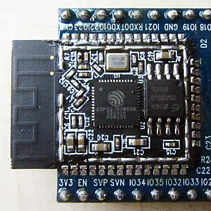
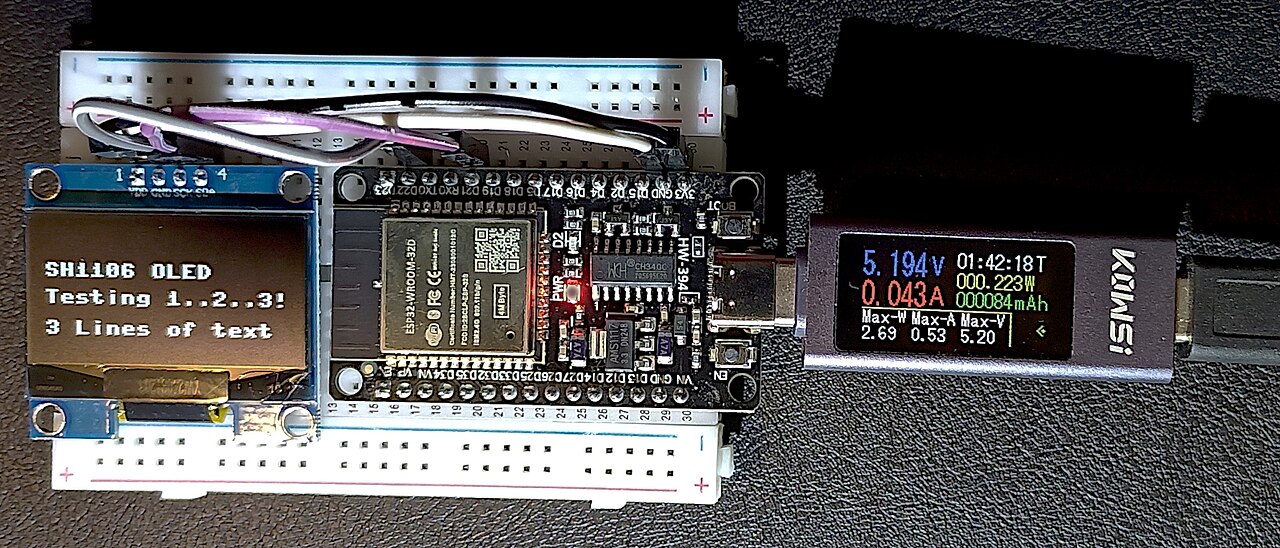
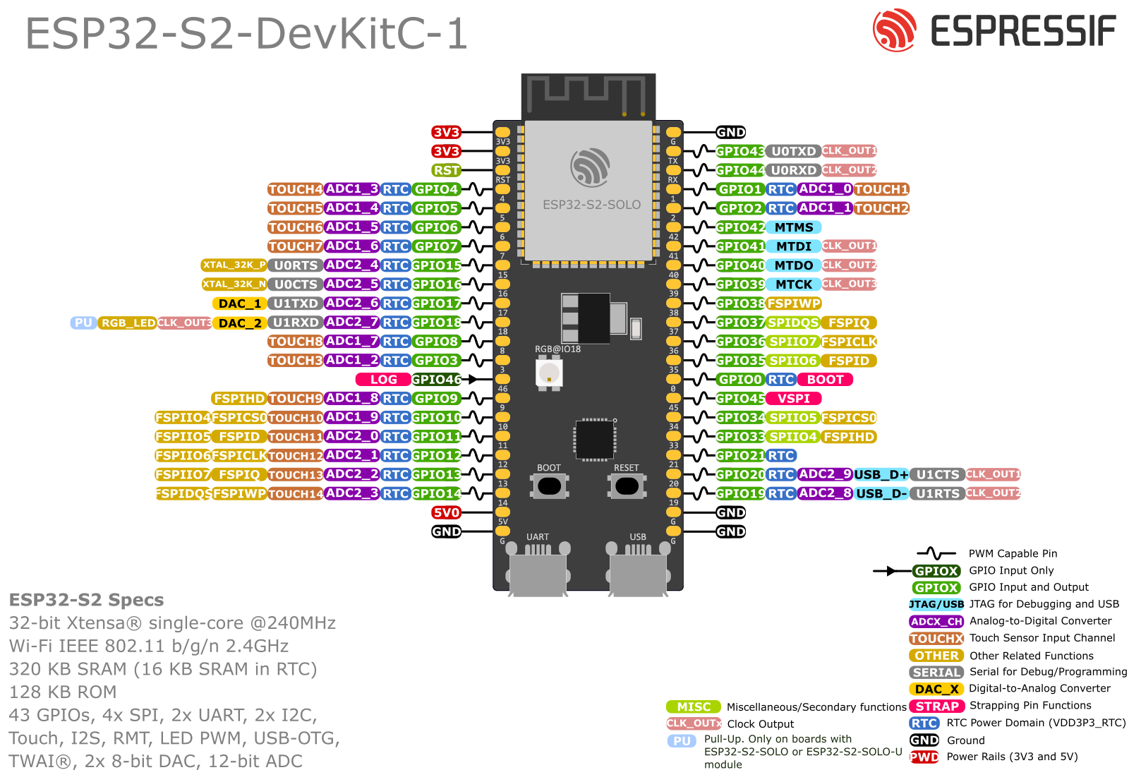
Pinout diagram
| Attr | Specs | verified |
|---|---|---|
cpu | single-core Tensilica Xtensa LX7 @ up to 240 MHz (160 MHz default in many configs); no GPU ( ESP32-S2 datasheet URL above). | ✔ |
memory | 320 KB internal SRAM, ~1.5 KB low-power SRAM, 448 KB ROM; external SPI flash up to 16 MB (4/8 MB typical); optional quad PSRAM (module-dependent) (ESP32-S2 datasheet: | ✔ |
connectivity | Wi-Fi 802.11 b/g/n 2.4 GHz (HT40, ESP-WIFI-MESH). No Bluetooth at all — a defining cut vs the ESP32 ( | ✔ |
usb | native USB-OTG (device + host) on GPIO19 (D−)/GPIO20 (D+) — flash/debug over USB without any bridge chip; basis of the QT-Py form factor ( | ✔ |
gpio | 43 programmable GPIOs, freely matrix-routed to USB-OTG, LCD (8080/SPI), 8-bit parallel camera interface, SPI, I2S, UART, ADC, DAC, touch (14 capacitive-touch GPIOs) ( - ADC: 12-bit SAR, up to 20 channels (ADC1 GPIO1–14 + ADC2); ADC2 blocked while Wi-Fi runs (datasheet URL above). - DAC: one 8-bit channel (GPIO17) (datasheet URL above). - LEDC PWM, RMT, motor-control PWM, SDIO master (datasheet URL above). | ✔ |
logic_level | 3.3 v | ? unverified |
power | deep sleep in the single-digit µA class with RTC wake; multiple low-power modes (datasheet URL above). > | ? unverified |
temperature | −40 °C to +105 °C ( | ✔ |
- Manufacturer: Espressif Systems (Shanghai) (
- Year: announced 2019, volume production from 2020 (first Wi-Fi-only member of the ESP32 family). >
- Status: Active product line, though Espressif has been consolidating kits: the ESP32-S2-DevKitM-1 was discontinued in favor of the ESP32-S2-DevKitC-1-N8R2, while MINI-2/2U module supply continues (
- Launch price: module street price ≈ US$2–4 (ESP32-S2-MINI-1 class); >
- Variants: chips ESP32-S2R8 (8 MB flash in-package), ESP32-S2FH32/FH16 etc. (flash/PSRAM combos); modules ESP32-S2-SOLO-1, ESP32-S2-MINI-1/-1U, ESP32-S2-MINI-2/-2U (
- Common boards: ESP32-S2-DevKitC-1, ESP32-S2-Kaluga-1 (display+camera), Adafruit QT Py / Feather / MagTag ESP32-S2, Espressif ESP32-S2-DevKitM-1 (legacy).
+ Strengths
- USB-OTG on an ESP32-class chip: USB CDC serial, HID keyboard/mouse, MIDI, mass market "USB dongle IoT" designs (
- 8-bit parallel camera + LCD interfaces — HMI/camera devices without the dual-core cost (
- Strongest security block of the 2019-era ESPs: RSA-3072 secure boot, XTS flash encryption, tamper-resistant key fusion, digital signature, HMAC (
- 14 capacitive touch channels + LCD → touch HMI niche (
- ESP RainMaker cloud platform launched around S2 (
− Weaknesses
- No Bluetooth: BLE provisioning apps written for ESP32 don't work; use SoftAP or USB provisioning (
- PSRAM vs Wi-Fi conflict: on S2, external PSRAM access is restricted while the Wi-Fi radio is active; ESP-IDF keeps critical buffers in internal RAM automatically, but naive "put everything in PSRAM" designs hit performance/feature limits (ESP-IDF PSRAM guide:
- ADC2 unusable with Wi-Fi (same family-wide quirk as ESP32) (
- Strapping pins GPIO0 / GPIO45 / GPIO46: GPIO45 controls VDD_SPI voltage and GPIO46 is boot-mode input; loading them at power-on causes "chip won't boot" (ESP32-S2 datasheet §Strapping Pins, URL above).
- GPIO33–GPIO37 may be consumed by the in-package flash/PSRAM on some variants (e.g. S2R8) — check your module's datasheet before committing pins (
- USB pins are precious: GPIO19/20 are the only USB pins; using them as GPIO loses native flashing on boards without a UART bridge (QT Py users must learn the boot+reset dance) (Adafruit QT Py guide:
- Kit churn: DevKitM-1 discontinued; docs/examples still reference it (
- Retour d'expérience expert expert — expert-microcontroleur
- Petit retour经验 sur l'ESP32-S2 après quelques mois d'utilisation. Le gros point fort reste le USB-OTG natif : pouvoir flasher et debugger sans pont UART est un gain de temps immense, surtout sur les formats compacts comme le QT Py. La sécurité (secure boot RSA-3072) est aussi très solide pour du pro… — expert-microcontroleur
- Merci pour le rappel sur le PSRAM, je galerais depuis quelques jours en pensant que c'etait mon code WiFi qui etaient trop lourd. Par contre, tu parles du USB-OTG comme d'un avantage, mais c'est une horreur quand on depasse le stade du devkit. Sur ma carte, j'ai utilise GPIO19 et 20 pour un petit c… — bricoleur_du_dimanche
- Pour le problème des pins GPIO19/20, il n'y a pas de magie. Une fois configurees en GPIO, tu perds l'interface native. La seule solution est d'utiliser un convertisseur USB-TTL sur d'autres pins pour le debug série, ou de laisser ces pins libres des le debut si tu veux la simplicite du flash par US… — maker_embedded
Community feedback and projects
- ESP32-S2 built-in temperature sensor forum.arduino.cc
- ESP32-S2 Feather & SD card forum.arduino.cc
- USB OTG and ESP32-S2 arduino.stackexchange.com
- Error in programming ESP32-S2-WROVER electronics.stackexchange.com
- esp32-s2_datasheet_en.pdf datasheet
- No Bluetooth: BLE provisioning apps written for ESP32 don't work; use SoftAP or USB provisioning (
- PSRAM vs Wi-Fi conflict: on S2, external PSRAM access is restricted while the Wi-Fi radio is active; ESP-IDF keeps critical buffers in internal RAM automatically, but naive "put everything in PSRAM" designs hit performance/feature limits (ESP-IDF PSRAM guide:
- ADC2 unusable with Wi-Fi (same family-wide quirk as ESP32) (
- Strapping pins GPIO0 / GPIO45 / GPIO46: GPIO45 controls VDD_SPI voltage and GPIO46 is boot-mode input; loading them at power-on causes "chip won't boot" (ESP32-S2 datasheet §Strapping Pins, URL above).
- GPIO33–GPIO37 may be consumed by the in-package flash/PSRAM on some variants (e.g. S2R8) — check your module's datasheet before committing pins (
- USB pins are precious: GPIO19/20 are the only USB pins; using them as GPIO loses native flashing on boards without a UART bridge (QT Py users must learn the boot+reset dance) (Adafruit QT Py guide:
- Kit churn: DevKitM-1 discontinued; docs/examples still reference it (
- Faire clignoter une LED avec l'ESP32-S2 debutant Schéma : IMG-esp32-s2-debutant-1-esp32-s2-clignotement-led.svg — Carte ESP32-S2, broche GPIO2 reliée via une résistance de 330 Ω à une LED dont la cathode va au GND.
- Lire un bouton poussoir avec anti-rebond debutant Schéma : IMG-esp32-s2-debutant-2-esp32-s2-bouton-anti-rebond.svg — Bouton poussoir entre le GPIO4 et le GND, résistance de pull-up interne activée par le programme sur la carte ESP32-S2.
- Console série et lecture d'un capteur analogique debutant Schéma : IMG-esp32-s2-debutant-3-esp32-s2-console-serie-capteur-analogique.svg — Potentiomètre dont le curseur est relié à l'entrée ADC1 GPIO3 d'une ESP32-S2, les deux autres pattes au 3V3 et au GND, câble USB vers l'ordinateur pour la console série.
- Scanner les réseaux WiFi environnants intermediaire Schéma : IMG-esp32-s2-intermediaire-1-esp32-s2-scan-wifi-reseaux.svg — ESP32-S2 reliée par câble USB à un ordinateur, la console série affiche la liste des réseaux WiFi 2,4 GHz détectés avec leur puissance de signal.
- Détecter un contact avec les broches tactiles capacitives intermediaire Schéma : IMG-esp32-s2-intermediaire-2-esp32-s2-tactile-capacitif.svg — Plaque de cuivre autocollante reliée au GPIO4 de l'ESP32-S2 servant de touche tactile capacitive, LED avec résistance de 330 Ω sur GPIO2, doigt posé sur la plaque.
- Stocker des journaux dans la flash avec LittleFS intermediaire Schéma : IMG-esp32-s2-intermediaire-3-esp32-s2-littlefs-logs.svg — ESP32-S2 dont la puce de flash embarquée est mise en évidence avec une icône de fichier journal, un capteur analogique sur GPIO3 et le câble USB vers la console série.
- Deep sleep à quelques microampères sur batterie avance Schéma : IMG-esp32-s2-avance-1-esp32-s2-deep-sleep-batterie.svg — ESP32-S2 alimentée par un pack de piles, bouton de réveil sur GPIO1 (réveil EXT0), LED témoin sur GPIO2, multimètre en série mesurant la consommation en microampères.
- Secure boot RSA-3072 et chiffrement de la flash avance Schéma : IMG-esp32-s2-avance-2-esp32-s2-secure-boot-chiffrement.svg — ESP32-S2 reliée en USB à un ordinateur, cadenas et bouclier au-dessus de la puce, icône de clé RSA-3072 et puce de flash chiffrée en AES-XTS.
- Serveur web embarqué pour piloter une LED avance Schéma : IMG-esp32-s2-avance-3-esp32-s2-serveur-web-led.svg — ESP32-S2 connectée au WiFi local, LED sur GPIO2 avec résistance de 330 Ω, un ordinateur et un smartphone affichent la page web servie par la carte avec boutons ON/OFF.
Code library — examples written for this board
clignotante.inoArduinobouton-led.inoArduinorespiration.inoArduinodht22.inoArduinooled-i2c.inoArduinoserveur-web.inoArduinotouch.inoArduinoservo.inoArduinosommeil-profond.inoArduinomesures.pyMicroPython
Examples and repos found online
- espressif/esp-idf github.com
- espressif/arduino-esp32 github.com
- espressif/esp-iot-solution github.com