M5StickC Plus2 (M5Stack) — ESP32-PICO-V3-02 "stick" wearable kit (SKU K016-P2)
⚡ The essentials in 60 seconds
- soc — Espressif ESP32-PICO-V3-02 system-in-package — dual-core 32-bit Xtensa LX6 @ up to 240 MHz ("SoC ESP32-PICO-V3-02@Dual-Core Processor, up to 240MHz", official specs; datasheet 520 KB SRAM on-die (ESP32 family, Espressif datasheet).
- gpu — none — LCD driven over SPI by the ST7789V2 display controller.
- memory — 8 MB SPI flash + 2 MB quad PSRAM, both inside the PICO-V3-02 SiP (official specs table; CNX op. cit.). (Predecessor Plus had 4 MB flash, no PSRAM — official comparison table.)
- storage — no SD/TF slot — code/data live in flash/LittleFS (official docs list no storage interface).
- wireless — Wi-Fi 802.11 b/g/n 2.4 GHz ("Wi-Fi 2.4 GHz Wi-Fi", official specs) + classic Bluetooth/BLE inherent to the ESP32 die (Espressif ESP32 datasheet 2.4 GHz 3D antenna (official specs).
- display — 1.14-inch 135×240 color TFT, driver ST7789V2; SPI: MOSI=G15, CLK=G13, DC=G14, RST=G12, CS=G5, BL=G27 (official PinMap "Color TFT Display").
- On this board : 9 tutorials · 10 code
The M5StickC Plus2 is a compact, pocket-sized development kit designed by M5Stack, a Shenzhen-based technology company. It belongs to the "Stick" family of devices, which are characterized by their TV-remote-like form factor, making them ideal for wearable projects, IoT controllers, and STEM education. The device measures just 48.0 mm in length, 24.0 mm in width, and 13.5 mm in thickness, weighing a mere 16.7 grams. Its plastic shell is orange, and it includes magnets and strap holes for easy mounting or wearing. At its core, the Plus2 is built around the Espressif ESP32-PICO-V3-02, a System-in-Package (SiP) microcontroller. A SiP means that the main processor, memory, and wireless components are integrated into a single compact package, saving board space. This specific chip features a dual-core 32-bit Xtensa LX6 processor running at up to 240 MHz. For context, a dual-core processor can handle two tasks simultaneously, which is useful for running a user interface while processing sensor data. The "240 MHz" refers to the clock speed, indicating how many cycles the processor can perform per second; higher speeds generally allow for faster processing of complex tasks. The chip includes 520 KB of on-die SRAM for fast temporary data storage.
One of the most significant upgrades in the Plus2 compared to its predecessors is its memory configuration. It comes with 8 MB of SPI flash storage and 2 MB of quad PSRAM (Pseudo-Static Random Access Memory). Flash storage is where your code and permanent data live, similar to a hard drive in a computer. PSRAM is a type of fast memory that allows the device to handle larger datasets and more complex graphics without slowing down. This is particularly important for running graphical user interfaces or buffering audio data. The device does not have an SD card slot, so all data must be stored in this internal flash or PSRAM. For wireless connectivity, the Plus2 supports Wi-Fi 802.11 b/g/n on the 2.4 GHz band and classic Bluetooth. The 2.4 GHz frequency is a common radio band used for home Wi-Fi networks, offering a good balance between range and speed. The device uses a 3D antenna to maintain a strong signal despite its small size.
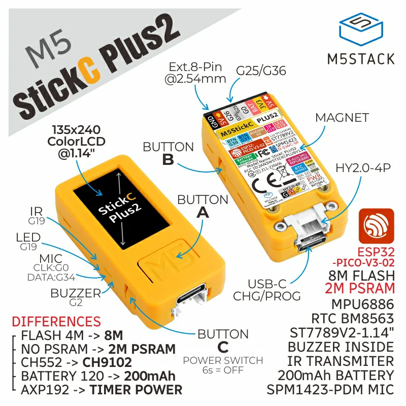
The user interface consists of a 1.14-inch color TFT display with a resolution of 135x240 pixels, driven by an ST7789V2 controller. While small, this screen is sufficient for displaying text, simple graphics, and status information. Input is provided by three physical buttons labeled A, B, and C. Button C is particularly important as it also serves as the power and reset switch. The device includes several sensors and peripherals that make it versatile. An IMU (Inertial Measurement Unit), specifically the MPU6886, provides 6-axis motion tracking (accelerometer and gyroscope), allowing the device to detect movement, tilt, and orientation. This is useful for gesture-controlled projects. An RTC (Real-Time Clock), the BM8563, keeps track of time even when the device is powered off or in deep sleep, thanks to the internal battery. Audio capabilities include a passive buzzer for generating tones and a MEMS PDM microphone (SPM1423) for capturing sound. The buzzer is "passive," meaning it requires the microcontroller to generate the frequency signal to produce sound, unlike an active buzzer which has its own oscillator.
Power management in the Plus2 is distinct from earlier versions. The v2 hardware revision, released in December 2023, removed the AXP192 PMIC (Power Management Integrated Circuit). A PMIC is a chip that manages power distribution and battery charging. By removing it, M5Stack simplified the power tree, which reportedly improved Wi-Fi and IR signal strength. Instead, power is controlled via a "HOLD" pin (G4). When the device is on, this pin must be held high to keep the power latched. If the firmware does not set this pin high after waking from sleep, the device will immediately shut down. This is a critical detail for developers to remember to avoid random reboot loops. The device is powered by a 200 mAh internal LiPo battery and charges via a USB Type-C port. It is important to note that when connected to USB, a long press of the power button only puts the screen to sleep; it does not fully cut power, which can lead to battery drain if left plugged in unnecessarily.
Expansion is facilitated through a HY2.0-4P Grove socket and an 8-pin external header. The Grove socket is compatible with the "Unit" series of sensors and modules, allowing for easy plug-and-play connections for additional functionality like temperature sensors or relays. The external header exposes several GPIO (General Purpose Input/Output) pins, which are programmable pins that can be used for digital or analog signals. However, users should be aware of some limitations. For instance, pins G25 and G26 are DAC (Digital-to-Analog Converter) pins and ADC2 channels. ADC2 channels cannot be used while Wi-Fi is active on the ESP32 classic silicon, so developers should prefer ADC1 pins (like G32, G33, or G36) for analog readings in Wi-Fi projects. Additionally, the IR emitter and the red LED share the same pin (G19), meaning they cannot be controlled independently; sending an IR signal will also flash the red LED.
The M5StickC Plus2 supports a wide range of development environments, including Arduino IDE, PlatformIO, ESP-IDF, and M5Stack's own UIFlow platforms. UIFlow allows for visual programming using blocks or MicroPython, making it accessible for beginners. For advanced users, C/C++ via Arduino or ESP-IDF offers full control. The device has a vibrant community, with popular third-party firmwares like Bruce and NEMO available, which transform the stick into a multi-tool for security testing or pranks. However, potential buyers should note that the product is currently marked as End-of-Life (EOL) on the official shop, meaning no future revisions are planned. Users should also be cautious of hardware revisions; the v1 and v2 models have different power architectures and libraries, so code written for one may not work on the other without modification. Despite these nuances, the Plus2 remains a highly integrated, affordable, and powerful tool for prototyping wearable electronics and IoT devices.
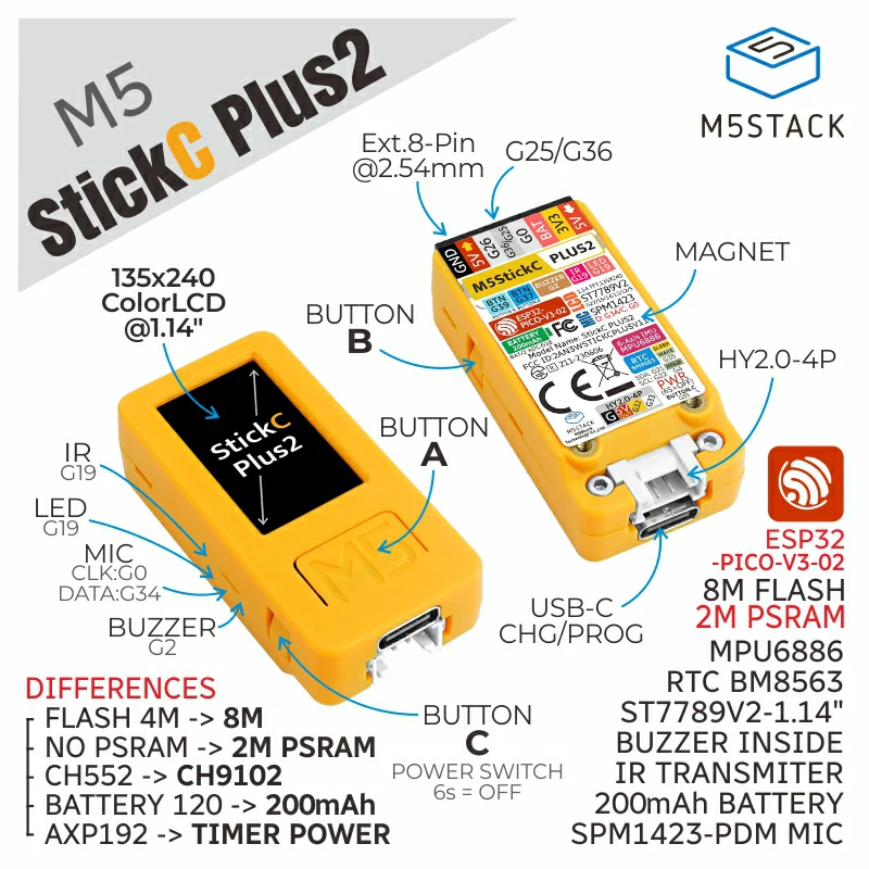
Pinout diagram
| Attr | Specs | verified |
|---|---|---|
soc | Espressif ESP32-PICO-V3-02 system-in-package — dual-core 32-bit Xtensa LX6 @ up to 240 MHz ("SoC ESP32-PICO-V3-02@Dual-Core Processor, up to 240MHz", official specs; datasheet 520 KB SRAM on-die (ESP32 family, Espressif datasheet). | ✔ |
gpu | none — LCD driven over SPI by the ST7789V2 display controller. | ? unverified |
memory | 8 MB SPI flash + 2 MB quad PSRAM, both inside the PICO-V3-02 SiP (official specs table; CNX op. cit.). (Predecessor Plus had 4 MB flash, no PSRAM — official comparison table.) | ? unverified |
storage | no SD/TF slot — code/data live in flash/LittleFS (official docs list no storage interface). | ? unverified |
wireless | Wi-Fi 802.11 b/g/n 2.4 GHz ("Wi-Fi 2.4 GHz Wi-Fi", official specs) + classic Bluetooth/BLE inherent to the ESP32 die (Espressif ESP32 datasheet 2.4 GHz 3D antenna (official specs). | ✔ |
display | 1.14-inch 135×240 color TFT, driver ST7789V2; SPI: MOSI=G15, CLK=G13, DC=G14, RST=G12, CS=G5, BL=G27 (official PinMap "Color TFT Display"). | ? unverified |
audio | passive buzzer on G2 (official PinMap "Passive Buzzer / G2"; tone output only — third-party firmware lists its speaker capability as "Tone", Bruce device table, MEMS PDM microphone SPM1423: CLK=G0, DATA=G34 (official PinMap "Microphone MIC (SPM1423)"; datasheet | ✔ |
sensors_misc_peripherals | - IMU MPU6886 6-axis (3-axis accel + 3-axis gyro) on I2C SDA=G21, SCL=G22 (official PinMap + specs). - RTC BM8563 on the same I2C bus (SDA=G21, SCL=G22) (official PinMap; datasheet - IR emitter + red LED share pin G19 (official specs: "Red LED x 1 (Shared control pin G19 with IR emitter tube)"; PinMap "IR Emitter & Red LED / G19"). - Buttons: A=G37 (front), B=G39 (side), C=G35 (power/reset, also the wake source) (official PinMap + "Pin Differences" table "BUTTON C (WAKE) G35"). - Green LED — non-programmable, wired as a sleep-state indicator (official specs: "Green LED x 1 (Non-programmable) (Sleep State Indicator)"). - Power HOLD pin = G4; battery voltage detect = G38 (official "Pin Differences" table). | ✔ |
expansion | - HY2.0-4P Grove socket ("PORT.CUSTOM": GND, 5V, G32, G33 — usable as I2C/I/O/UART) (official PinMap + specs "HY2.0-4P (I2C+I/O+UART) x 1"). - 8-pin external header exposing G0, G25/G26, G36 (official specs "External Pins G0, G25/G26, G36, G32, G33"; CNX lists the shared pair as "G25/G36" — see Problems). - Front HAT stacking header + Unit series compatibility ("the interface is compatible with both HAT and Unit series modules", official description). | ? unverified |
power | USB Type-C 5 V @ 500 mA input; 200 mAh @ 3.7 V internal LiPo; no PMIC on v2 (AXP192 removed in 2023.12) — power latching is done with the HOLD (G4)/3V3EN circuit instead (official specs + version-change table; CNX op. cit.). USB-serial bridge: CH9102 (official "USB Driver" section; CNX). | ? unverified |
power_on_off_logic_v2 | power-on = hold BUTTON C > 2 s, or RTC IRQ wake — after a wake the firmware must drive HOLD (G4)=1 or the unit shuts back down; power-off (no USB) = hold C > 6 s or HOLD=0 in software; with USB connected, long-press C only sleeps the screen (official "Operation Instructions"). | ? unverified |
gpio_electrical_esp32_classic_silicon | 3.3 V logic. G32/G33/G36 are ADC1 channels (ADC1_CH4/CH5/CH0); G25/G26 are the DAC pins and ADC2 channels (ADC2 is unusable while Wi-Fi runs — Espressif ADC doc G35/G37/G39 are input-only pins (fine for the buttons); G4 is HOLD; G2 is a strapping pin (ESP32 datasheet, op. cit.). PWM available on most outputs (buzzer on G2 uses PWM tone); no external PWM/ADC header beyond the 8-pin port. | ✔ |
mechanical | 48.0 × 24.0 × 13.5 mm, 16.7 g, plastic (PC) shell, orange; magnets and strap/lanyard mount for wearable use ("Wearable & mountable", official features; magnets/screw holes noted in the official shop page review text). | ? unverified |
operating_temperature | 0 °C to 40 °C (official specs). > | ? unverified |
power_consumption | ? unverified |
- Manufacturer: M5Stack (Shenzhen M5Stack Technology Co., Ltd.) — product "StickC-Plus2", SKU K016-P2 (official docs page,
- Released: first release 2021 (the official version-change table dates v1.1 "added sleep and wake-up functions" at 2021.12, so v1.0 predates it; exact first-release month is not stated in the official table). >
- Price: US$19.95 on the official shop at the v2 launch (CNX Software, 2023-12-13, op. cit. — "same price as the M5Stick PLUS devkit"). >
- Status: EOL (end-of-life) — the official shop product page is titled "[EOL] M5StickC PLUS2 ESP32 Mini IoT Development Kit" (retrieved 2026-10-13, Related current stick products on the shop include the M5StickC Plus SE (US$19.00, and the StickS3 line.
- Revisions/variants (same SKU, different hardware generations) — official version-change table (docs.m5stack.com, op. cit.): - v1.0 (2021) — ESP32-PICO-D4 + AXP192 PMIC (the v2 change note says the main controller was "changed from ESP32-PICO-D4 to ESP32-PICO-V3-02" and AXP192 was "removed"). - v1.1 (2021.12) — added sleep and wake-up functions. - v2 (2023.12, current) — ESP32-PICO-V3-02, no PMIC, new power on/off method, improved Wi-Fi and IR signal strength (official docs: "Wi-Fi and IR signal strength have both been improved compared to the previous model"). - Predecessor for comparison: M5StickC Plus (ESP32-PICO-D4, AXP192, 120 mAh, CH522 USB chip, red-orange shell); Plus2 is orange, 200 mAh, CH9102, 8 MB flash + 2 MB PSRAM (official "Hardware Differences" table, docs.m5stack.com, op. cit.).
+ Strengths
- All-in-one "stick" wearable: IR blaster + RTC + PDM mic + 6-axis IMU + buzzer + TFT + 3 buttons + 200 mAh battery in 16.7 g / 48 mm (official description & specs) — the most peripheral-dense device in the Stick line at its price.
- ESP32-PICO-V3-02 SiP with 8 MB flash + 2 MB PSRAM — 2× the flash and the first PSRAM in the StickC family, enabling camera-less audio buffering, LVGL UIs and large payload buffers (official comparison table vs StickC-Plus).
- PMIC-free power architecture (v2): removing the AXP192 improved Wi-Fi and IR signal strength (official docs) and simplified the power tree to a HOLD/3V3EN latch with RTC wake — deep-sleep wakeups are driven by the BM8563 RTC IRQ and must re-assert HOLD (G4) in firmware (official Operation Instructions).
- Dual expansion: front HAT stacking header (M5 HAT modules, e.g. IR/DMX/relay HATs) and rear HY2.0-4P Grove socket for the whole Unit sensor line (official description "compatible with both HAT and Unit series modules").
- IR emitter on G19 shared with the red LED — one pin drives both the blaster and its own status light (official PinMap).
- RTC-backed timekeeping: BM8563 keeps time through deep sleep/off states; community firmware uses it as a real clock (NEMO: "clock backed by the M5 Stick RTC so it holds relatively stable time even in deep sleep",
- Huge pentest-firmware ecosystem: first-class target of Bruce, NEMO and the M5Launcher bootloader (device support tables:
- Wearable & mountable: magnets + strap holes, marketed for wearables/IoT controllers/STEM (official features & applications).
− Weaknesses
- Two incompatible hardware generations under one name: v1 (2021, ESP32-PICO-D4 + AXP192) vs v2 (2023.12, ESP32-PICO-V3-02, no PMIC) — different SoC, different power on/off method, and "the supported libraries will differ" (official version-change table + comparison note). Code written for the Plus/Plus2-v1 AXP192 APIs (e.g. M5.Power.* of the old M5StickCPlus library) does not apply to v2.
- HOLD-pin trap on wake: after an RTC wake-up the unit powers back off unless the program sets HOLD (G4)=1 immediately — sleep/wake examples that forget this look like random reboot loops (official Operation Instructions).
- "Power off" with USB connected is only sleep: long-press C > 6 s while on USB turns the screen off but does not cut power (official Operation Instructions) — users report "won't turn off / battery drains on charger".
- Power-off mechanism is not the HOLD pin alone: the button hardware pulls 3V3EN low to kill the 3.3 V DC/DC (green LED on = 3V3EN low); POWER_HOLD_PIN alone does not replicate a button power-off (M5Stack community:
- C-to-C cable → port not recognized: documented official workaround — power off (green LED), then re-plug (official "Note"). Wrong/missing CH9102 driver gives the same "no COM port" symptom (official USB Driver section).
- G19 shared by IR emitter and red LED: any IR transmission toggles the red LED and vice-versa; you cannot use them independently (official specs/PinMap).
- Shared external pin pair: the official spec writes the external pins as "G0, G25/G26, G36, G32, G33" while CNX writes "G25/G36, G26"; the family library README warns "G36/G25 share the same port, when one of the pins is used, the other pin should be set as a floating input" — battery/external analog reads on those pins fail in Wi-Fi projects; prefer G32/G33/G36 (ADC1).
- Buzzer sits on G2, a strapping pin (ESP32 datasheet) — keep the buzzer circuit unloaded at boot; external loads on the G2 header net can block boot.
- Buttons A/B/C are on input-only pins G37/G39/G35 (official PinMap; ESP32 datasheet) — no output capability, no internal pull-downs on these pins.
- Green LED is not programmable — only a sleep-state indicator; code that "blinks the green LED" silently does nothing (official specs).
- Deprecated device library: m5stack/M5StickCPlus2 is marked "🚫 Deprecated — Use M5GFX & M5Unified" ( old tutorials' #include <M5StickCPlus2.h> still compiles but is unmaintained.
- Black screen after flashing community examples: "green LED turns on, but nothing comes on the screen" when running M5StickC(Plus) examples on a Plus2 — wrong board/display init (community report:
- Product is EOL on the official shop (page title "[EOL]", retrieved 2026-10-13) — no future revisions; buy spares early.
- Spec-sheet disagreements to be aware of: operating temperature (official 0–40 °C vs CNX 0–60 °C) and CNX's spec bullet still listing "AXP192 PMU" while its own text and the official docs say the PMIC was removed (CNX op. cit. vs official version-change table).
- Tiny buttons: the 3 buttons are small and hard to press — usability, not a bug (official shop page review text).
- ESP32-classic platform issues apply generally (ADC nonlinearity, ADC2/Wi-Fi conflict, strapping-pin boot traps): official errata
- Retour d'expérience expert expert — expert-microcontroleur
- Retour d'expérience sur la StickC-Plus2 (v2 ESP32-PICO-V3-02). Attention au piège du HOLD pin (G4) : si vous sortez de deep sleep via le RTC BM8563, votre code doit immédiatement mettre G4 à 1, sinon la carte s'éteint et vous avez l'impression d'être dans une boucle de reboot. C'est documenté mais … — expert-microcontroleur
- Merci pour le rappel sur le HOLD pin, j'ai perdu deux heures à comprendre pourquoi ma routine de réveil ne tenait pas. J'ai un autre souci : ma carte n'est plus détectée par le PC via USB-C. J'ai beau changer de câble, rien. Dans la doc, il est mentionné qu'il faut éteindre la carte (LED verte allu… — hobbyiste-bricoleur
- Pour ton problème de port USB, vérifie bien que le driver CH9102 est installé, c'est souvent l'oubli classique. Sinon, oui, l'extinction complète est impossible tant que le 5V est présent sur le port USB, le circuit de latch ne coupe pas l'alim externe, seul le mode veille s'active. Concernant les … — maker-debutant-77
Community feedback and projects
- Mini Slot Machine Project with M5StickC Plus2 forum.clockworkpi.com
- Most featured ESP32 per cm2 - M5StickC Plus review notenoughtech.com
- CanAirIO Bike hackaday.io
- Sch_M5StickC_Plus2_v0.5.pdf pdf
- BM8563_V1.1_cn.pdf datasheet
- esp32-pico_series_datasheet_en.pdf datasheet
- MPU-6886-000193+v1.1_GHIC_en.pdf datasheet
- SPM1423HM4H-B_datasheet_en.pdf datasheet
- ST7789V.pdf datasheet
- Official product page (specs, PinMap, power logic, PlatformIO, drivers)
- Shop (EOL listing)
- Schematic
- Datasheets
- Datasheets
- Datasheets
- Datasheets
- Datasheets
- Datasheets
- Libraries
- Libraries
- Libraries
- Libraries
- Quick-starts & guides
- Quick-starts & guides
- Quick-starts & guides
- Quick-starts & guides
- Quick-starts & guides
- Firmware/projects
- Firmware/projects
- Firmware/projects
- Firmware/projects
- Firmware/projects
- Community
- Community
- Platform
- Platform
- Platform
- Press
- Press
- Two incompatible hardware generations under one name: v1 (2021, ESP32-PICO-D4 + AXP192) vs v2 (2023.12, ESP32-PICO-V3-02, no PMIC) — different SoC, different power on/off method, and "the supported libraries will differ" (official version-change table + comparison note). Code written for the Plus/Plus2-v1 AXP192 APIs (e.g. M5.Power.* of the old M5StickCPlus library) does not apply to v2.
- HOLD-pin trap on wake: after an RTC wake-up the unit powers back off unless the program sets HOLD (G4)=1 immediately — sleep/wake examples that forget this look like random reboot loops (official Operation Instructions).
- "Power off" with USB connected is only sleep: long-press C > 6 s while on USB turns the screen off but does not cut power (official Operation Instructions) — users report "won't turn off / battery drains on charger".
- Power-off mechanism is not the HOLD pin alone: the button hardware pulls 3V3EN low to kill the 3.3 V DC/DC (green LED on = 3V3EN low); POWER_HOLD_PIN alone does not replicate a button power-off (M5Stack community:
- C-to-C cable → port not recognized: documented official workaround — power off (green LED), then re-plug (official "Note"). Wrong/missing CH9102 driver gives the same "no COM port" symptom (official USB Driver section).
- G19 shared by IR emitter and red LED: any IR transmission toggles the red LED and vice-versa; you cannot use them independently (official specs/PinMap).
- Shared external pin pair: the official spec writes the external pins as "G0, G25/G26, G36, G32, G33" while CNX writes "G25/G36, G26"; the family library README warns "G36/G25 share the same port, when one of the pins is used, the other pin should be set as a floating input" — battery/external analog reads on those pins fail in Wi-Fi projects; prefer G32/G33/G36 (ADC1).
- Buzzer sits on G2, a strapping pin (ESP32 datasheet) — keep the buzzer circuit unloaded at boot; external loads on the G2 header net can block boot.
- Buttons A/B/C are on input-only pins G37/G39/G35 (official PinMap; ESP32 datasheet) — no output capability, no internal pull-downs on these pins.
- Green LED is not programmable — only a sleep-state indicator; code that "blinks the green LED" silently does nothing (official specs).
- Deprecated device library: m5stack/M5StickCPlus2 is marked "🚫 Deprecated — Use M5GFX & M5Unified" ( old tutorials' #include <M5StickCPlus2.h> still compiles but is unmaintained.
- Black screen after flashing community examples: "green LED turns on, but nothing comes on the screen" when running M5StickC(Plus) examples on a Plus2 — wrong board/display init (community report:
- Product is EOL on the official shop (page title "[EOL]", retrieved 2026-10-13) — no future revisions; buy spares early.
- Spec-sheet disagreements to be aware of: operating temperature (official 0–40 °C vs CNX 0–60 °C) and CNX's spec bullet still listing "AXP192 PMU" while its own text and the official docs say the PMIC was removed (CNX op. cit. vs official version-change table).
- Tiny buttons: the 3 buttons are small and hard to press — usability, not a bug (official shop page review text).
- ESP32-classic platform issues apply generally (ADC nonlinearity, ADC2/Wi-Fi conflict, strapping-pin boot traps): official errata
- Afficher du texte sur l'écran 135×240 debutant Schéma : IMG-m5stack-stick-c-plus-2-debutant-1-m5stick-c2-afficher-texte.svg — M5StickC Plus2 orange vu de face, écran 1,14" affichant des lignes de texte vertes, flèches vers l'écran ST7789 et les boutons A et B.
- Réagir aux boutons A et B debutant Schéma : IMG-m5stack-stick-c-plus-2-debutant-2-m5stick-c2-boutons-a-b.svg — Vue de profil de la M5StickC Plus2 avec les boutons A (face, G37), B (flanc, G39) et C (alimentation, G35) annotés et un compteur affiché à l'écran.
- Lire l'accélération avec l'IMU MPU6886 debutant Schéma : IMG-m5stack-stick-c-plus-2-debutant-3-m5stick-c2-imu-acceleration.svg — M5StickC Plus2 inclinée avec vecteurs X, Y, Z d'accélération et bus I2C interne (SDA=G21, SCL=G22) reliant l'IMU MPU6886 et l'horloge RTC BM8563.
- Tracer une courbe d'accélération en temps réel intermediaire Schéma : IMG-m5stack-stick-c-plus-2-intermediaire-1-m5stick-c2-courbe-imu.svg — Écran de la M5StickC Plus2 en paysage 240×135 affichant une courbe défilante de la norme d'accélération avec grille de repères et tampon circulaire de 240 échantillons.
- Enregistreur de mouvement sur mémoire flash (LittleFS) intermediaire Schéma : IMG-m5stack-stick-c-plus-2-intermediaire-2-m5stick-c2-enregistreur-littlefs.svg — Coupe de la M5StickC Plus2 montrant la puce SiP ESP32-PICO-V3-02 et ses 8 Mo de flash avec le système de fichiers LittleFS, l'IMU écrivant des lignes CSV, sans emplacement carte SD.
- Se connecter au Wi-Fi et interroger une API HTTP intermediaire Schéma : IMG-m5stack-stick-c-plus-2-intermediaire-3-m5stick-c2-wifi-http.svg — M5StickC Plus2 reliée par une onde Wi-Fi 2,4 GHz à un routeur puis à un serveur HTTP, l'écran affichant la température récupérée en JSON.
- Réveil par mouvement et économie d'énergie (HOLD/RTC) avance Schéma : IMG-m5stack-stick-c-plus-2-avance-1-m5stick-c2-eveil-mouvement.svg — M5StickC Plus2 en cycle veille/réveil : broche HOLD G4 à 1 pendant l'activité, relâchée en veille, réveil par IRQ du RTC BM8563, avec la consigne « remettre HOLD=1 sinon réextinction ».
- Micro PDM et buzzer : sonomètre interactif avance Schéma : IMG-m5stack-stick-c-plus-2-avance-2-m5stick-c2-micro-pdm.svg — M5StickC Plus2 avec le microphone MEMS PDM SPM1423 (CLK=G0, DATA=G34) qui capte une onde sonore, jauge de niveau sur l'écran, et buzzer passif sur G2 relié en PWM.
- Nœud MQTT : télémétrie IMU et commandes à distance avance Schéma : IMG-m5stack-stick-c-plus-2-avance-3-m5stick-c2-mqtt-dashboard.svg — M5StickC Plus2 publiant ses données IMU vers un broker MQTT, un téléphone et un ordinateur abonnés aux topics, et recevant un ordre de bipeur en retour.
Code library — examples written for this board
hello-stick.inoArduinoboutons.inoArduinobuzzer.inoArduinoinclinometre.inoArduinohorloge.inoArduinoir-tv.inoArduinosonometre.inoArduinopodometre.inoArduinobatterie.inoArduinostick_imu.pyMicroPython
Examples and repos found online
- m5stack/M5StickCPlus2 github.com
- m5stack/M5Unified github.com
- m5stack/M5GFX github.com