Raspberry Pi Model B+ (2014) — Board Sheet
⚡ The essentials in 60 seconds
- soc — unchanged Broadcom BCM2835 — single-core 32-bit ARM1176JZF-S (ARMv6, VFPv2) @ 700 MHz + VideoCore IV GPU (~250 MHz; OpenGL ES 2.0, ~24 GFLOPS; 1080p30 H.264 encode/decode; MPEG-2/VC-1 licensed). (Wikipedia)
- ram — 512 MB LP-DDR shared CPU/GPU. (Wikipedia)
- storage — microSD card slot (replaces the full-size SD of Model A/B). (Wikipedia)
- connectivity — 1× 10/100 Mbps Ethernet + 4× USB 2.0 — still all behind one LAN9514 hub/NIC combo on the single 480 Mbps USB 2.0 bus. HDMI (full-size), combined 3.5 mm 4-pole AV jack (composite video + analog audio) replacing the separate RCA + audio jacks. No WiFi/Bluetooth. (Wikipedia)
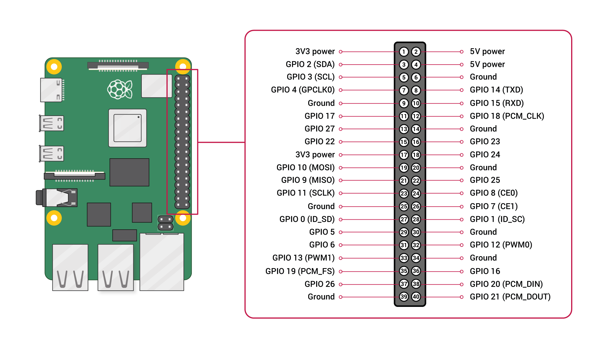
- gpio — 40-pin header (J8) — the now-standard pinout: 3.3 V/5 V rails, GND, ID_SD/ID_SC, I²C0 (fixed) + I²C0/1 muxable, SPI0 + SPI1 (aux), UART0, hardware PWM (GPIO18), 28 usable GPIOs; 3.3 V logic, no ADC/DAC. Electrically compatible with 26-pin Pi 1 HATs (with adapter caveats). (Wikipedia; pinout.xyz)
- power — micro-USB 5 V; the B+ power circuitry was redesigned to be markedly more efficient than the Model B (the launch announcement advertised a large reduction in board power consumption).
- On this board : 9 tutorials · 10 code
Launched on July 14, 2014, the Raspberry Pi Model B+ represents a pivotal moment in the history of single-board computers, serving as the definitive template for the "Model B" form factor that continues to this day. Developed by the Raspberry Pi Foundation in the United Kingdom and manufactured at the Sony Pencoed plant in Wales, this board was introduced at a price of thirty-five US dollars. Its primary significance lies not in raw processing power, but in its refined physical design and connectivity options, which established the standard layout for all subsequent Raspberry Pi models. While it has since been superseded by the Pi 2, 3, 4, and 5, the Model B+ remains a legacy device of great historical and educational interest, particularly for understanding the evolution of embedded Linux systems.
At the heart of the Model B+ is the Broadcom BCM2835 system-on-chip, an architecture that remained unchanged from the original Raspberry Pi Model B. This chip features a single-core ARM1176JZF-S processor based on the ARMv6 instruction set, running at a clock speed of 700 MHz. For those unfamiliar with technical specifications, the clock speed refers to how many cycles the processor can execute per second; 700 MHz means it can perform 700 million cycles per second. While this may seem low by modern standards, it was sufficient for the lightweight Linux distributions of its time. The system is paired with 512 MB of LP-DDR RAM, which is shared between the central processor and the VideoCore IV graphics processing unit. This shared memory architecture means that the total available memory is fixed, and using more for graphics leaves less for running applications. The GPU supports OpenGL ES 2.0 and can handle 1080p video playback, making it capable of serving as a basic media center.
One of the most notable improvements of the Model B+ over its predecessors was the transition from a full-size SD card slot to a microSD card slot. This change allowed for a more compact board layout and aligned the device with the storage standards becoming prevalent in mobile devices. The board measures 65 by 56 millimeters and includes four mounting holes positioned in a way that became the standard for future Raspberry Pi models, facilitating easier integration into cases and projects. Power is supplied via a micro-USB connector, and the power circuitry was redesigned to be significantly more efficient than the original Model B. Although the exact percentage of power reduction claimed in the 2014 announcement is noted as unverified in current documentation, the improved efficiency was a key selling point, reducing the heat generated and allowing for more stable operation in enclosed spaces.
Connectivity was greatly expanded with the introduction of four USB 2.0 ports, doubling the number available on the previous Model B. However, it is crucial to understand that these ports, along with the 10/100 Mbps Ethernet port, all share a single USB 2.0 bus via a LAN9514 chip. This means that the total bandwidth available to all USB devices and the network connection is limited to 480 Mbps combined. In real-world scenarios, this can create bottlenecks if multiple high-speed devices are connected simultaneously. The board also features a full-size HDMI port for video output and a combined 3.5 mm four-pole jack that handles both composite video and analog audio, replacing the separate RCA and audio jacks found on earlier models. It is important to note that the Model B+ does not include built-in WiFi or Bluetooth, requiring users to rely on wired Ethernet or external USB adapters for wireless connectivity.
The most enduring legacy of the Model B+ is its 40-pin general-purpose input/output (GPIO) header, designated as J8. This header standardized the pinout for all future Raspberry Pi boards, providing a consistent interface for hardware enthusiasts and educators. The 40-pin layout includes various power rails (3.3V and 5V), ground connections, and multiple communication interfaces such as I2C, SPI, and UART. Specifically, it offers two I2C interfaces, two SPI interfaces, and a UART port, along with hardware PWM (Pulse Width Modulation) on GPIO18. PWM is a technique used to control the average power delivered to an electrical device, often used for controlling servo motors or dimming LEDs. The header also includes ID_SD and ID_SC pins, which allow for the automatic identification of HATs (Hardware Attached on Top), add-on boards that plug directly into the GPIO header. While the 40-pin header is electrically compatible with older 26-pin HATs using adapters, there are mechanical and logical caveats, such as the need to keep the ID pins unconnected for proper HAT detection.
Software support for the Model B+ has evolved since its launch. Originally running Raspbian, which was later renamed Raspberry Pi OS, the board also supported RISC OS, Ubuntu MATE, and other distributions. Today, the official Raspberry Pi OS has dropped support for the ARMv6 architecture in its newer versions (Bullseye and later), meaning users must rely on legacy 32-bit images, such as those based on Debian Buster, or specialized distributions like RetroPie and LibreELEC that still maintain ARMv6 builds. The boot process relies on a microSD card with a FAT partition containing the bootloader, as the BCM2835 chip lacks an EEPROM for USB booting. This means that all operating system files must reside on the SD card, which can be a point of failure if the card is corrupted or removed improperly.
Despite its age, the Model B+ remains a viable platform for specific projects, particularly those that benefit from its multiple USB ports and wired network connection. It was a popular choice for Pi-hole network ad blockers, OctoPrint servers for 3D printers, and retro gaming consoles using RetroPie. The availability of four USB ports allowed for the connection of a printer, a webcam, and other peripherals without needing a hub. However, users should be aware of its limitations, including the 512 MB RAM ceiling, which can make modern desktop environments sluggish, and the potential for thermal throttling if the board exceeds 85 degrees Celsius. Additionally, early firmware issues related to the SD card host controller were resolved over time through updates, but they highlight the importance of keeping the firmware up to date. The Model B+ stands as a testament to the Raspberry Pi Foundation's commitment to creating affordable, accessible computing hardware, and its design choices continue to influence the ecosystem of single-board computers today.
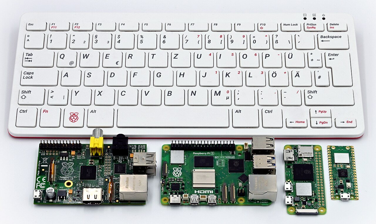
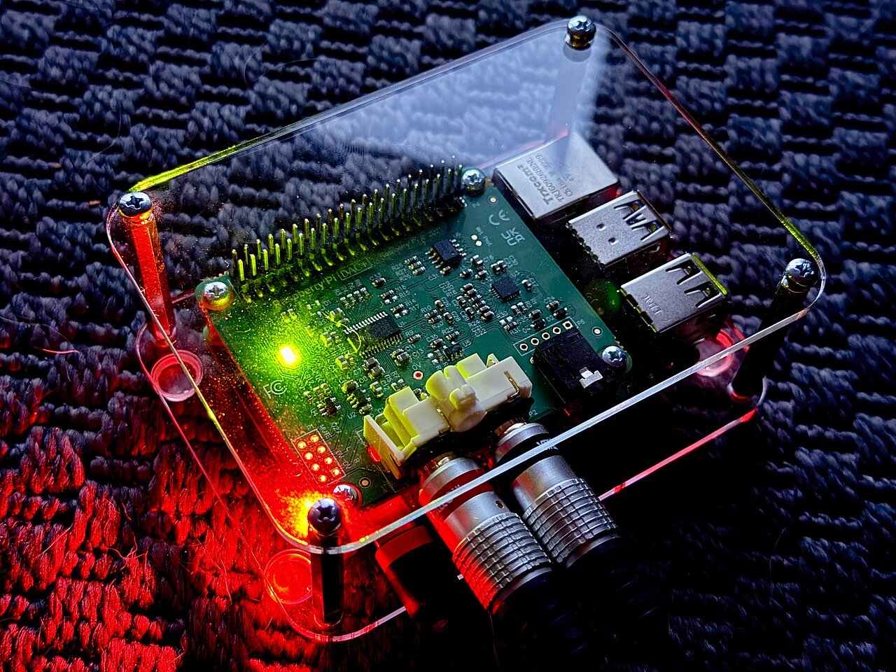
Pinout diagram
| Attr | Specs | verified |
|---|---|---|
soc | unchanged Broadcom BCM2835 — single-core 32-bit ARM1176JZF-S (ARMv6, VFPv2) @ 700 MHz + VideoCore IV GPU (~250 MHz; OpenGL ES 2.0, ~24 GFLOPS; 1080p30 H.264 encode/decode; MPEG-2/VC-1 licensed). (Wikipedia) | ✔ |
ram | 512 MB LP-DDR shared CPU/GPU. (Wikipedia) | ✔ |
storage | microSD card slot (replaces the full-size SD of Model A/B). (Wikipedia) | ✔ |
connectivity | 1× 10/100 Mbps Ethernet + 4× USB 2.0 — still all behind one LAN9514 hub/NIC combo on the single 480 Mbps USB 2.0 bus. HDMI (full-size), combined 3.5 mm 4-pole AV jack (composite video + analog audio) replacing the separate RCA + audio jacks. No WiFi/Bluetooth. (Wikipedia) | ✔ |
gpio | 40-pin header (J8) — the now-standard pinout: 3.3 V/5 V rails, GND, ID_SD/ID_SC, I²C0 (fixed) + I²C0/1 muxable, SPI0 + SPI1 (aux), UART0, hardware PWM (GPIO18), 28 usable GPIOs; 3.3 V logic, no ADC/DAC. Electrically compatible with 26-pin Pi 1 HATs (with adapter caveats). (Wikipedia; pinout.xyz) | ✔ |
power | micro-USB 5 V; the B+ power circuitry was redesigned to be markedly more efficient than the Model B (the launch announcement advertised a large reduction in board power consumption). | ? unverified |
temperature | firmware throttles above 85 °C or on undervoltage. (Wikipedia) | ✔ |
mechanical | 65 × 56 mm with four mounting holes aligned to the future Pi 2/3/4 standard. (Wikipedia) | ✔ |
- Manufacturer / developer: Raspberry Pi (Trading) Ltd. / Raspberry Pi Foundation, UK, with Broadcom; built at the Sony Pencoed plant, Wales. (Wikipedia, retrieved 2026-10-13)
- Launch: 14 July 2014 at US$35 — "a refined design featuring additional USB ports and a more efficient board layout that established the form factor for future models". (Wikipedia; announcement (archived), 14 Jul 2014)
- Price cut: $25 on 14 May 2015, after the Pi 2 arrived. (Wikipedia; blog: "Price Cut! Raspberry Pi Model B+ Now Only $25")
- Status: End-of-life / legacy (superseded by Pi 2/3/4/5 Model B), but its board outline, 40-pin header and 4-USB layout define every "Model B" since. (Wikipedia)
- Variants: B+ (BCM2835, 512 MB); sibling Model A+ (Nov 2014, $20, no Ethernet). Revision codes 0010 (and later). (Wikipedia)
+ Strengths
- Defined the modern Pi form factor: 40-pin header, microSD, 4 USB, combined AV jack, mounting-hole positions — all later Model B boards inherit this layout. (Wikipedia)
- 4× USB without sacrificing the $35 price (vs 2 on Model B). (Wikipedia)
- 40-pin header extras: second I²C, second SPI, UART pairing and ID EEPROM pins for HAT auto-identification. (pinout.xyz)
- Cheapest 4-USB Linux SBC after the 2015 price cut ($25). (official blog)
- Same 1080p60-class H.264 encode/decode hardware as the Pi 1 line. (Wikipedia)
− Weaknesses
- All USB + Ethernet share one 480 Mbps port (LAN9514): four devices + network contend; real-world combined throughput is far below the port count suggests. (Wikipedia)
- 512 MB RAM ceiling unchanged — modern desktop use is painful; headless or lightweight X recommended. (Wikipedia)
- Polyfuse/undervoltage: over-current trips still cause weak-power symptoms; 85 °C/brown-out throttling applies. (eLinux R-Pi Troubleshooting)
- microSD transition quirks: early B+ SD-host issues (card detection/clock edge cases) were a 2014–2015 forum theme; fixed via firmware sdhost/dtoverry tweaks over time.
- HAT compatibility trap: 26-pin-era add-ons mechanically don't fit the 40-pin board edge; and ID_SD/ID_SC pins must stay unconnected for HAT detection. (pinout.xyz)
- No WiFi/Bluetooth — unlike the Pi 3 generation it competes with second-hand. (Wikipedia)
- Retour d'expérience expert expert — expert-raspberrypi
- Petit retour d'experience sur la Model B+ après quelques mois d'utilisation en projet domotique. Le facteur forme est vraiment l'atout majeur ici : le connecteur 40 pin et les 4 ports USB ont defini la norme pour tous les Modele B subsequent, ce qui facilite grandement la compatibilite materielle a… — expert-raspberrypi
- Merci pour ce retour, ca confirme mes doutes sur les perfs réseau. Je viens de recevoir ma B+ pour un projet media center basique. Tu dis que le port micro-SD a donne du fil a retordre au debut ? J'ai lu des trucs sur des problèmes de detection de carte. C'est toujours d'actu ou c'est corrige par l… — maker_hobbyiste
- Salut, pour completer sur les alimentations : fais gaffe a la sous-tension. Si ton alim est juste, le polyfuse saute ou tu as des brown-outs qui font planter le système quand tu branches trop de peripheriques. Vu que tout partage le bus, un disque USB gourmand peut suffire a destabiliser l'ensemble… — electro_nov1ce
Community feedback and projects
- The ASUS Tinker Board is a compelling upgrade from a Raspberry Pi 3 B+ jeffgeerling.com
- Add a dirt-cheap screen to the Raspberry Pi B+ blog.reasonablycorrect.com
- I finally found a use case for my Raspberry Pi Model B+ ounapuu.ee
- The making of the Raspberry Pi Model B+ raspi.today
- Raspberry Pi B+ hackaday.com
- Official projects site
- Pi-hole
- OctoPrint print server
- RetroPie console
- Network music player (MoOde/MusicBot era)
- Adafruit 40-pin GPIO + PWM servo guide
Content not available yet.
- All USB + Ethernet share one 480 Mbps port (LAN9514): four devices + network contend; real-world combined throughput is far below the port count suggests. (Wikipedia)
- 512 MB RAM ceiling unchanged — modern desktop use is painful; headless or lightweight X recommended. (Wikipedia)
- Polyfuse/undervoltage: over-current trips still cause weak-power symptoms; 85 °C/brown-out throttling applies. (eLinux R-Pi Troubleshooting)
- microSD transition quirks: early B+ SD-host issues (card detection/clock edge cases) were a 2014–2015 forum theme; fixed via firmware sdhost/dtoverry tweaks over time.
- HAT compatibility trap: 26-pin-era add-ons mechanically don't fit the 40-pin board edge; and ID_SD/ID_SC pins must stay unconnected for HAT detection. (pinout.xyz)
- No WiFi/Bluetooth — unlike the Pi 3 generation it competes with second-hand. (Wikipedia)
- Allumer une LED depuis la GPIO 17 avec libgpiod debutant Schéma : IMG-model-b-plus-debutant-1-modelbp-led-gpio.svg — Raspberry Pi Model B+ et son en-tête 40 broches : GPIO17 (broche 11) vers résistance 330 Ω puis LED, cathode reliée au GND (broche 14).
- Lire un bouton et afficher les appuis dans la console debutant Schéma : IMG-model-b-plus-debutant-2-modelbp-bouton-console.svg — bouton-poussoir entre GPIO27 (broche 13) et GND (broche 20), pull-up interne activé par gpio=27=pup dans config.txt.
- Premier script Python : faire clignoter la LED debutant Schéma : IMG-model-b-plus-debutant-3-modelbp-premier-python.svg — même LED que le tuto 1 sur GPIO17 (broche 11) avec résistance 330 Ω et GND broche 14, éditeur de texte et terminal lançant blink.py.
- Variation d'intensité d'une LED avec le PWM matériel (GPIO18) intermediaire Schéma : IMG-model-b-plus-intermediaire-1-modelbp-pwm-led.svg — LED avec résistance 330 Ω sur GPIO18 (broche 12), la broche PWM matérielle du BCM2835, GND en broche 14 ; le signal carré 200 Hz est dessiné en encart.
- Interroger un capteur I2C (BME280) sur le bus du 40 broches intermediaire Schéma : IMG-model-b-plus-intermediaire-2-modelbp-i2c-capteur.svg — capteur BME280 relié au bus I2C0 : SDA sur broche 3 (GPIO2), SCL sur broche 5 (GPIO3), VCC 3,3 V (broche 1) et GND (broche 6), avec les résistances de pull-up du module.
- Mettre le B+ en réseau par Ethernet et piloter en SSH intermediaire Schéma : IMG-model-b-plus-intermediaire-3-modelbp-reseau-ssh.svg — Raspberry Pi Model B+ relié par câble Ethernet à une box/routeur (pas de WiFi ni Bluetooth embarqués), un ordinateur portable se connectant en SSH, l'adresse IP affichée sur l'écran.
- Amorçage microSD, pannes de boot et procédure de recouvrement avance Schéma : IMG-model-b-plus-avance-1-modelbp-boot-sd-recouvrement.svg — étapes de l'amorçage du BCM2835 : ROM de démarrage lisant bootcode.bin sur la partition FAT de la microSD, puis kernel.img et config.txt ; à côté, un PC relisant la carte via adaptateur pour la réparer.
- Surveiller température et bridage : le BCM2835 à l'épreuve avance Schéma : IMG-model-b-plus-avance-2-modelbp-surveillance-thermique.svg — Raspberry Pi Model B+ avec son SoC BCM2835 souligné, sonde de température et jauges fréquence 700 MHz / seuil de bridage 85 °C, un graphique température-temps en encart et l'éclair de sous-tension.
- Serveur web léger et partage de fichiers (NAS) sur bus USB partagé avance Schéma : IMG-model-b-plus-avance-3-modelbp-serveur-web-nas.svg — Raspberry Pi Model B+ servant une page web et un partage Samba : un disque USB et le câble Ethernet convergent vers la puce unique LAN9514 branchée sur l'unique bus USB 2.0 de 480 Mbit/s.
Code library — examples written for this board
led_blink.pyPythonbutton_led.pyPythonservo_sweep.pyPythondht_temp.pyPythonoled_i2c.pyPythonmcp3008_read.pyPythoncam_photo.pyPythonweb_led.pyPythongpiotools_blink.shBashblink_c.cC
Examples and repos found online
- raspberrypi/noobs github.com
- WiringPi/WiringPi github.com
- joan2937/pigpio github.com
- raspberrypi/userland github.com