Raspberry Pi Pico 2 W
⚡ The essentials in 60 seconds
- mcu — Raspberry RP2350A (SDK board header sets PICO_RP2350A 1) — two Arm Cortex-M33 (ARMv8-M, with FPU single-precision + simplified DP coprocessor, DSP, TrustZone) or two Hazard3 RISC-V (RV32IMAC) cores, user-selectable at runtime via ARCHSEL, @ 150 MHz; 40 nm process; 7×7 mm QFN-60 (Pico 2 W datasheet §1, pico2_w.h board header, Wikipedia — RP2350).
- gpu — none. New HSTX (high-speed serial transmit) peripheral for digital video output: 8 pins @ 300 Mb/s DDR (Wikipedia — RP2350; Pico 2 W datasheet §1).
- ram — 520 KB SRAM on-chip in ten concurrently-accessible banks; 16 KB XIP cache; 8 KB antifuse OTP (Pico 2 W datasheet §1, Wikipedia — RP2350).
- storage — 4 MB external QSPI flash with XIP ("RP2350 microcontroller with 4 MB of flash memory"; SDK PICO_FLASH_SIZE_BYTES (4 1024 1024); Pico 2 datasheet: "double the on-board flash (2 MB → 4 MB)") (Pico 2 W datasheet §1, pico2_w.h, Pico 2 datasheet §2).
- wireless — Infineon CYW43439, single-band 2.4 GHz Wi-Fi 4 (802.11n) with WPA3, SoftAP (up to 4 clients), Bluetooth 5.2 (LE Central + Peripheral roles and Bluetooth Classic); connected to the RP2350 via SPI typically running at 33 MHz; on-board antenna is an Abracon (formerly ProAnt) Niche licensed design (Pico 2 W datasheet §1, §3.8, launch blog).
- wired — USB 1.1 (LS/FS, device and host) via micro-USB B; 3-pin SWD debug port (SWDIO/SWCLK have ~60 kΩ internal pull-ups) (Pico 2 W datasheet §3.7, §3.9).
- On this board : 9 tutorials · 10 code
The Raspberry Pi Pico 2 W, launched on November 25, 2024, represents a significant evolution in the world of low-cost microcontrollers, offering wireless connectivity at an accessible price point of seven US dollars. As the wireless variant of the Pico 2, it is built around the RP2350A microcontroller, a second-generation chip from Raspberry Silicon that introduces a unique dual-architecture capability. This means the board features two processor cores that can be configured to run either Arm Cortex-M33 or Hazard3 RISC-V instructions. This flexibility allows developers to choose the instruction set that best fits their project’s needs without changing the hardware, a feature that is quite rare in this price range. The chip operates at 150 MHz and is manufactured using a 40 nm process, providing a balance of performance and power efficiency suitable for a wide array of embedded applications.
Memory resources on the Pico 2 W are substantial for a microcontroller of its class. It includes 520 KB of on-chip SRAM, which is divided into ten banks that can be accessed concurrently, reducing bottlenecks during complex operations. Additionally, there is a 16 KB cache for execute-in-place operations, allowing code to run directly from the external flash memory without needing to be copied to RAM first. The board comes with 4 MB of external QSPI flash storage, which is double the capacity of its predecessor, the original Pico. This increased storage allows for larger applications and more extensive data logging capabilities. It is worth noting that while some internal documentation inconsistencies have been identified regarding the flash size, multiple authoritative sources, including the software development kit and key feature lists, confirm the 4 MB specification.
The defining feature of this board, however, is its wireless capability, provided by the Infineon CYW43439 chip. This module supports single-band 2.4 GHz Wi-Fi 4 (802.11n) with WPA3 security, ensuring modern encryption standards are met. It also supports Bluetooth 5.2, including both Low Energy and Classic Bluetooth roles, which is unusual for such an inexpensive device. The wireless module connects to the main microcontroller via an SPI interface running at 33 MHz. The antenna is an on-board design licensed from Abracon, requiring careful attention to physical placement; a 14 by 9 mm keep-out zone must remain clear of any materials or metal enclosures to maintain signal integrity. Unlike some other boards, there is no option for an external antenna connector, as Raspberry Pi determined that adding one would complicate global radio frequency certifications.
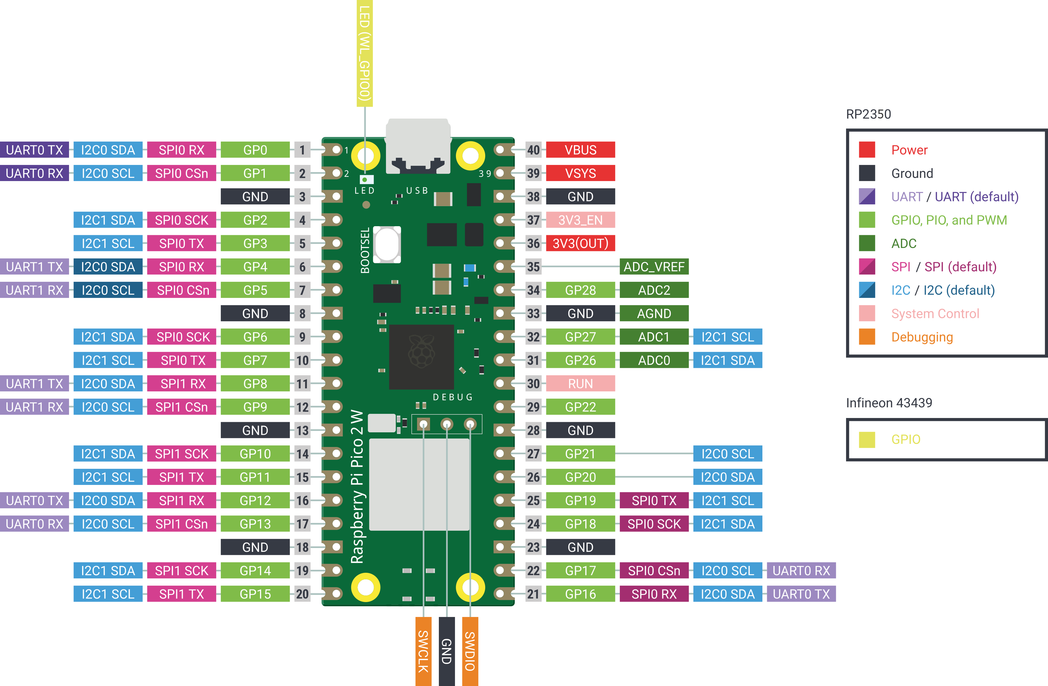
Programming the Pico 2 W is versatile, with official support for C/C++ via the pico-sdk, as well as MicroPython, CircuitPython, and Arduino. MicroPython support became official with version 1.25.0 in April 2025, resolving earlier gaps where only unofficial builds were available. For those using C/C++, the board is identified by the flag PICO_BOARD=pico2_w, which automatically configures the necessary libraries for Wi-Fi and Bluetooth. A critical aspect of programming this board is understanding its pin configuration. While it exposes 26 of the RP2350’s 30 GPIO pins on its 40-pin header, four pins—GP23 through GP25 and GP29—are reserved for internal communication with the wireless module. Specifically, GP25 is used as the chip select for the wireless SPI interface. This means that traditional blink code, which often toggles GP25, will interfere with the radio’s operation. Instead, the on-board LED is connected to the wireless chip itself, requiring specific API calls to control it, a detail that distinguishes the Pico 2 W from its non-wireless siblings.
Power management is another area where the Pico 2 W offers flexibility, particularly for battery-powered IoT projects. The board features a buck-boost power converter that accepts an input voltage between 1.8 and 5.5 volts on the VSYS pin, regulating it to a stable 3.3 volts for the microcontroller and external components. This wide input range allows the board to be powered by various battery chemistries or directly from USB. The power system includes features for efficiency, such as pulse-frequency modulation, and supports power-path management for simultaneous charging and operation. However, users should be aware of a subtle hardware interaction: the analog-to-digital converter channel used to monitor the battery voltage shares a pin with the wireless clock signal. Consequently, reading the battery level while the Wi-Fi is actively transmitting data can yield inaccurate results unless specific software protections are employed.
The board’s physical design is compact, measuring 51 by 21 millimeters, and it is designed to be soldered directly onto a larger circuit board as a surface-mount module. This makes it suitable for product development, where the Pico 2 W can be integrated into custom hardware. The schematic and PCB design are open hardware, with the exception of the antenna design, which remains licensed. Raspberry Pi has committed to keeping the board available until at least January 2028, providing stability for long-term projects. While the board is generally robust, early revisions were affected by a silicon erratum related to GPIO leakage current, which has been addressed in software and corrected in later chip steppings. Additionally, the analog-to-digital converter has an inherent offset of approximately 30 millivolts due to its power supply filtering, a factor that must be accounted for in high-precision measurement applications.
Despite its capabilities, the Pico 2 W has limitations. The Wi-Fi is restricted to the 2.4 GHz band, lacking support for the less congested 5 GHz frequency, and throughput is bounded by the shared SPI link. Furthermore, the board does not include an operating system; it is a bare-metal microcontroller, meaning developers must manage resources and concurrency manually or use a real-time operating system like Zephyr, which also supports this board. The community has already developed various projects, from industrial OPC UA servers to wireless game controller bridges, demonstrating the board’s versatility. For those new to the platform, the official documentation and example code provide a solid foundation, though care must be taken to adapt legacy code that assumes standard GPIO assignments. Overall, the Raspberry Pi Pico 2 W stands out as a powerful, affordable, and flexible tool for developers seeking to add wireless connectivity to their embedded projects, balancing performance with cost in a highly competitive market.
Pinout diagram
| Attr | Specs | verified |
|---|---|---|
mcu | Raspberry RP2350A (SDK board header sets PICO_RP2350A 1) — two Arm Cortex-M33 (ARMv8-M, with FPU single-precision + simplified DP coprocessor, DSP, TrustZone) or two Hazard3 RISC-V (RV32IMAC) cores, user-selectable at runtime via ARCHSEL, @ 150 MHz; 40 nm process; 7×7 mm QFN-60 (Pico 2 W datasheet §1, pico2_w.h board header, Wikipedia — RP2350). | ✔ |
gpu | none. New HSTX (high-speed serial transmit) peripheral for digital video output: 8 pins @ 300 Mb/s DDR (Wikipedia — RP2350; Pico 2 W datasheet §1). | ✔ |
ram | 520 KB SRAM on-chip in ten concurrently-accessible banks; 16 KB XIP cache; 8 KB antifuse OTP (Pico 2 W datasheet §1, Wikipedia — RP2350). | ✔ |
storage | 4 MB external QSPI flash with XIP ("RP2350 microcontroller with 4 MB of flash memory"; SDK PICO_FLASH_SIZE_BYTES (4 1024 1024); Pico 2 datasheet: "double the on-board flash (2 MB → 4 MB)") (Pico 2 W datasheet §1, pico2_w.h, Pico 2 datasheet §2). | ✔ |
wireless | Infineon CYW43439, single-band 2.4 GHz Wi-Fi 4 (802.11n) with WPA3, SoftAP (up to 4 clients), Bluetooth 5.2 (LE Central + Peripheral roles and Bluetooth Classic); connected to the RP2350 via SPI typically running at 33 MHz; on-board antenna is an Abracon (formerly ProAnt) Niche licensed design (Pico 2 W datasheet §1, §3.8, launch blog). | ✔ |
wired | USB 1.1 (LS/FS, device and host) via micro-USB B; 3-pin SWD debug port (SWDIO/SWCLK have ~60 kΩ internal pull-ups) (Pico 2 W datasheet §3.7, §3.9). | ✔ |
gpio_board | 40-pin 0.1″ castellated/through-hole header exposing 26 of the RP2350's 30 GPIO, fixed 3.3 V logic (1.8–3.3 V I/O on the chip); GP0–GP22 digital-only; GP26–GP28 digital + ADC. GP23–GP25 and GP29 are consumed by the radio (see Features/Problems): GP23 = WL power-on, GP24 = wireless SPI data/IRQ (shared), GP25 = wireless SPI CS, GP29 = wireless SPI CLK shared with ADC3 = VSYS/3 monitor (Pico 2 W datasheet §1, §2.1, §3.8, pico2_w.h). | ✔ |
peripherals_chip | 2 × UART, 2 × SPI, 2 × I²C, 16 PWM channels (8 dual units on the A die), 4-channel 12-bit 500 kSPS SAR ADC + internal temperature sensor, 16-channel DMA, 3 PIO blocks / 12 state machines, 1 timer + 4 alarms + AON timer, hardware SHA-256 accelerator and TRNG (Pico 2 W datasheet §1, Wikipedia — RP2350). | ✔ |
board_adc_notes | no on-chip reference — ADC_AVDD is the filtered 3.3 V SMPS rail (201 Ω × 2.2 µF), giving an inherent ~30 mV offset (≈150 µA × 200 Ω); fixes: ground-channel offset subtraction, forcing PWM SMPS mode (drive WL_GPIO1 high), or an external 3.0 V shunt reference (e.g. LM4040) on ADC_VREF. GP26–GP29 have a reverse diode to IOVDD (max ≈3.6 V; back-powers an unpowered board) (Pico 2 W datasheet §3.2–3.3). | ✔ |
power | VBUS 5 V ±10% (micro-USB) → Schottky → VSYS 1.8–5.5 V → RT6154 buck-boost SMPS → 3V3 (also powers external circuitry; keep load < 300 mA); PFM default / PWM forced via WL_GPIO1; 3V3_EN (pin 37) disables the SMPS; VBUS present sensed on WL_GPIO2; battery-charger and P-FET power-ORing patterns documented (Pico 2 W datasheet §3.4–3.6). | ✔ |
consumption | the Pico 2 W datasheet has no power table; the Pico 2 datasheet (same board family, radio-less) gives typical VBUS@5 V: low-power states P1.0–P1.7 = 148–233 µA, RUN-low 388 µA, USB-boot idle 5.47 mA, hello_serial ≈12.4 mA, single-core CoreMark ≈9.38 mA (Pico 2 datasheet §4.1). | ✔ |
temperature_reliability | recommended operating −20 °C to +70 °C (including self-heating); MTBF 182,000 h (ground benign) / 11,000 h (ground mobile) (Pico 2 W datasheet §2.3, App. C). | ✔ |
mechanical | single-sided 51 × 21 × 1 mm PCB, 40 × 0.1″ dual in-line/castellated pins, 4 × 2.1 mm mounting holes, reflow-solderable as an SMT module (paste stencil 163 % over-paste recommended); 14 × 9 mm antenna keep-out cutout at the bottom edge — no material may intrude, no metal enclosure (Pico 2 W datasheet §2, §2.2.1). | ✔ |
- Manufacturer: Raspberry Pi Ltd (UK). Wireless variant of the Pico 2, built around Raspberry Silicon's second-generation MCU (launch blog "Raspberry Pi Pico 2 W on sale now at $7"; Pico 2 W datasheet).
- Year: launched 25 November 2024 ("our epic autumn of product launches continues"; blog comment timestamps 25 Nov 2024; datasheet Documentation Release History: "25 November 2024 — Initial release") (launch blog, Pico 2 W datasheet, App. D).
- Status: Active. Availability guaranteed "until at least January 2028" (Pico 2 W datasheet, Appendix A).
- Price: launch price US$7 (blog title "…on sale now at $7"; confirmed by Wikipedia — Raspberry Pi: "The Pico 2 W adds Wi-Fi and Bluetooth at US$7").
- Variants: within the Pico 2 series: Pico 2 (US$5, SC1631) and Pico 2 with headers (SC1632, US$6; the Pico 2 datasheet's table row is mislabeled "Raspberry Pi Pico with headers") (Pico 2 datasheet, App. A.2). The Pico 2 W itself is sold without pin headers (solder-pad option for reflow as an SMT module); Raspberry Pi's PIP portal lists a "Pico 2 with headers" category but no header'ed Pico 2 W (PIP categories). Third-party variants exist, e.g. Pimoroni Pico Plus 2 W (uses Raspberry Pi's upcoming RM2 radio module) (launch blog).
+ Strengths
- Dual-architecture RP2350: pick Cortex-M33 or Hazard3 RISC-V per core-reset (ARCHSEL); all four cores reachable without power-cycle. Unique at this price (Wikipedia — RP2350).
- Same proven radio as Pico W: Infineon CYW43439 — and unusually for a $7 MCU, Bluetooth Classic alongside BLE 5.2; WPA3 and 4-client SoftAP (launch blog, Pico 2 W datasheet §3.8).
- Transparent security model: Arm TrustZone for Cortex-M, signed boot ROM, 8 KB antifuse OTP, SHA-256 accelerator, hardware TRNG, fast glitch detectors, and a hardened redundancy coprocessor (RCP) against fault injection (Pico 2 datasheet §2, Wikipedia — RP2350).
- Security proven (mostly) in public: Raspberry Pi's DEF CON 32 hacking challenge ($10,000, doubled, for reading RP2350 OTP) ended in January 2025 with four winners using laser fault injection and focused-ion-beam readout — i.e. no remote software exploit (Wikipedia — RP2350).
- HSTX video peripheral + 12 PIO state machines (vs 8 on RP2040) — DVI/RGB display generation without the CPU (Wikipedia — RP2350, CircuitPython board page).
- On-board LED hangs off the radio chip (CYW43 WL_GPIO0), not the RP2350 — the SDK deliberately defines no PICO_DEFAULT_LED_PIN; blink code must go through cyw43_arch_gpio_put(CYW43_WL_GPIO_LED_PIN, …) (pico2_w.h, pico-examples README).
- Flexible powerchain for battery IoT: 1.8–5.5 V VSYS buck-boost (RT6154), documented diode/P-FET power-ORing and power-path-charger hookups, VBUS sensing, PFM/PWM efficiency control (Pico 2 W datasheet §3.4–3.6).
- Open hardware — with one exception: schematic/PCB released freely, but the Niche antenna design is Abracon-licensed and excluded (Pico 2 W datasheet §1.1).
- Productization path: same footprint usable as a reflow SMT module; Raspberry Pi's RM2 certified radio module is the scale-up route for designs prototyped on this board (Pico 2 W datasheet §2.2, launch blog).
− Weaknesses
- RP2350-E9 silicon erratum (affects early boards): "Increased leakage current on Bank 0 GPIO when pad input is enabled" (originally documented as latching pulldowns) — input-configured pins source ~120 µA mid-rail and can hold pins near 2.2 V; high-impedance inputs and internal pulldowns are affected (use ≤8.2 kΩ external pulldowns). Reported by users incl. the Bus Pirate team; the SDK builds RP2350-A2 workarounds by default (PICO_RP2350_A2_SUPPORTED 1 in pico2_w.h). Fixed in A3/A4 steppings announced 29 July 2025 (Wikipedia — RP2350 "GPIO hardware issue", pico-feedback issue #401, RP2350 datasheet p.1342, CircuitPython board page note, A4 announcement blog).
- Classic Pico blink code is wrong on this board: the LED is on the CYW43 (WL_GPIO0), and GP25 is the wireless SPI chip-select — poking GP25 like a Pico/Pico 2 LED toggles the radio's CS line. Use picow_blink-style code (cyw43_arch_gpio_put(CYW43_WL_GPIO_LED_PIN, …)) (pico2_w.h, pico-examples README: blink vs blink_simple vs picow_blink).
- GP23–GP25 and GP29 are not free GPIOs: they carry the radio's power-on, shared data/IRQ, CS and CLK/VSYS-monitor lines; the datasheet explicitly lists them as internal functions (Pico 2 W datasheet §2.1).
- VSYS monitoring collides with Wi-Fi: ADC3 (VSYS/3 on GP29) shares the wireless SPI clock — "only when there isn't an SPI transaction in progress can VSYS be read"; the SDK requires wrapping VSYS ADC reads in cyw43_thread_enter/exit (CYW43_USES_VSYS_PIN 1), so naive battery monitoring reads garbage while the radio is busy (Pico 2 W datasheet §3.8, pico2_w.h).
- Launch-day software gap: at release (Nov 2024) there was no official MicroPython or CircuitPython firmware; users had to flash an explicitly "unofficial" Raspberry Pi build, and the launch blog carries an update notice about it. Official MicroPython landed only in v1.25.0 (April 2025) (launch blog update banner, MicroPython v1.25.0).
- Multi-core Wi-Fi event loss (fixed in MicroPython 1.25.0): "Lost WiFi events due to code executing on the second core" was a documented bug fixed in that release — older firmware releases drop radio events when core 1 runs user code (v1.25.0 release notes, rp2 section).
- ADC accuracy by design: ~30 mV inherent offset from the 150 µA × 200 Ω ADC supply filter, SMPS ripple coupling, offset varies with sampling/temperature; GP26–GP29 reverse diode to IOVDD (≤ ~3.6 V, back-powering hazard) — identical traps to Pico/Pico 2 (Pico 2 W datasheet §3.2–3.3).
- RF/antenna constraints: 14 × 9 mm keep-out, board must sit at the board edge, metal nearby (or a metal case = Faraday cage) degrades gain/bandwidth; no external-antenna option — Raspberry Pi explains an antenna connector would break worldwide RF certification (Pico 2 W datasheet §2.2.1, §3.8, launch blog comment from James Hughes, 25 Nov 2024).
- Zephyr quirks: Wi-Fi needs manually fetched proprietary CYW43439 firmware + CLM (country-code) blobs, and the stock blinky sample "is not yet supported on Pico 2W" (Zephyr board docs).
- Wi-Fi ceiling: the CYW43439 is 2.4 GHz Wi-Fi 4 (802.11n) only — no 5 GHz, and throughput is bounded by the shared ~33 MHz SPI link to the RP2350 (Pico 2 W datasheet §3.8).
- USB host power caveat: in USB-host mode you must feed 5 V to the VBUS pin; the datasheet gives no host 5 V output current figure (Pico 2 W datasheet §3.5).
- Retour d'expérience expert expert — expert-raspberrypi
- Retour d'experience sur la Pico 2 W. Le prix de 7 dollars est imbattable pour avoir du Bluetooth Classic et du BLE 5.2, mais attention aux pieges materiels. Si vous avez un lot d'arrivee, verifiez la revision du silicon RP2350. Les premières versions (E9) souffrent d'une fuite de courant sur les GP… — expert-raspberrypi
- Merci pour le rappel sur GP25, j'ai perdu une heure a comprendre pourquoi mon module radio ne repondait plus des que je touchais a la LED. J'ai une question sur la mesure de tension. Je veux surveiller ma batterie via l'ADC, mais j'ai lu que GP29 est partage avec l'horloge SPI du WiFi. Est-ce que j… — makers_bidouilleur
- Exactement, c'est une collision materielle connue. GP29 porte a la fois le signal VSYS/3 pour l'ADC et l'horloge SPI du module无线. Vous ne pouvez lire la tension que lorsqu'aucune transaction SPI n'est en cours. Si vous essayez de lire pendant que la radio communique, vous obtenez des ordures. Dans … — expert-raspberrypi
Community feedback and projects
- DigiKeyコーヒーカップ:Raspberry Pico 2 または Raspberry Pico 2 W のMicropython forum.digikey.com
- lwip include path for Raspberry Pi pico 2 w SDK stackoverflow.com
- Inky Frame 7.3″ is a 7-color ePaper display powered by a Raspberry Pi Pico 2 W cnx-software.com
- Unable to use SD card with Pico 2 W but the same wiring and code works with Pico W raspberrypi.stackexchange.com
- How do i get Nema 17 motor to work with DRV8825 and Pico 2 W? raspberrypi.stackexchange.com
- PIP RP-008304
- pip.raspberrypi.com/categories/1088-raspberry-pi-pico-2-w
- RP-008306 schematic PDF
- RP-008305 pinout
- datasheets.raspberrypi.com/pico/pico-2-datasheet.pdf
- datasheets.raspberrypi.com/rp2350/rp2350-datasheet.pdf
- raspberrypi.com/news/raspberry-pi-pico-2-w-on-sale-now
- raspberrypi.com/products/raspberry-pi-pico-2-w
- raspberrypi.com/documentation/microcontrollers/pico-series.html
- MicroPython quickref
- rptl.io/pico-get-started
- rptl.io/pico-c-sdk
- rptl.io/picow-connect
- raspberrypi/pico-sdk
- src/boards/include/boards/pico2_w.h
- pico-examples
- pico-sdk-tools (picotool, RISC-V toolchain)
- errata feedback issue #401
- RPI_PICO2_W downloads
- raspberry_pi_pico2_w
- earlephilhower/arduino-pico
- Zephyr rpi_pico2 board docs
- rp-rs rp-hal
- GitHub topic pico-2-w
- Wikipedia — RP2350
- Wikipedia — Raspberry Pi
- RP2350 A4/RP2354 blog (29 Jul 2025)
- RP2350-E9 silicon erratum (affects early boards): "Increased leakage current on Bank 0 GPIO when pad input is enabled" (originally documented as latching pulldowns) — input-configured pins source ~120 µA mid-rail and can hold pins near 2.2 V; high-impedance inputs and internal pulldowns are affected (use ≤8.2 kΩ external pulldowns). Reported by users incl. the Bus Pirate team; the SDK builds RP2350-A2 workarounds by default (PICO_RP2350_A2_SUPPORTED 1 in pico2_w.h). Fixed in A3/A4 steppings announced 29 July 2025 (Wikipedia — RP2350 "GPIO hardware issue", pico-feedback issue #401, RP2350 datasheet p.1342, CircuitPython board page note, A4 announcement blog).
- Classic Pico blink code is wrong on this board: the LED is on the CYW43 (WL_GPIO0), and GP25 is the wireless SPI chip-select — poking GP25 like a Pico/Pico 2 LED toggles the radio's CS line. Use picow_blink-style code (cyw43_arch_gpio_put(CYW43_WL_GPIO_LED_PIN, …)) (pico2_w.h, pico-examples README: blink vs blink_simple vs picow_blink).
- GP23–GP25 and GP29 are not free GPIOs: they carry the radio's power-on, shared data/IRQ, CS and CLK/VSYS-monitor lines; the datasheet explicitly lists them as internal functions (Pico 2 W datasheet §2.1).
- VSYS monitoring collides with Wi-Fi: ADC3 (VSYS/3 on GP29) shares the wireless SPI clock — "only when there isn't an SPI transaction in progress can VSYS be read"; the SDK requires wrapping VSYS ADC reads in cyw43_thread_enter/exit (CYW43_USES_VSYS_PIN 1), so naive battery monitoring reads garbage while the radio is busy (Pico 2 W datasheet §3.8, pico2_w.h).
- Launch-day software gap: at release (Nov 2024) there was no official MicroPython or CircuitPython firmware; users had to flash an explicitly "unofficial" Raspberry Pi build, and the launch blog carries an update notice about it. Official MicroPython landed only in v1.25.0 (April 2025) (launch blog update banner, MicroPython v1.25.0).
- Multi-core Wi-Fi event loss (fixed in MicroPython 1.25.0): "Lost WiFi events due to code executing on the second core" was a documented bug fixed in that release — older firmware releases drop radio events when core 1 runs user code (v1.25.0 release notes, rp2 section).
- ADC accuracy by design: ~30 mV inherent offset from the 150 µA × 200 Ω ADC supply filter, SMPS ripple coupling, offset varies with sampling/temperature; GP26–GP29 reverse diode to IOVDD (≤ ~3.6 V, back-powering hazard) — identical traps to Pico/Pico 2 (Pico 2 W datasheet §3.2–3.3).
- RF/antenna constraints: 14 × 9 mm keep-out, board must sit at the board edge, metal nearby (or a metal case = Faraday cage) degrades gain/bandwidth; no external-antenna option — Raspberry Pi explains an antenna connector would break worldwide RF certification (Pico 2 W datasheet §2.2.1, §3.8, launch blog comment from James Hughes, 25 Nov 2024).
- Zephyr quirks: Wi-Fi needs manually fetched proprietary CYW43439 firmware + CLM (country-code) blobs, and the stock blinky sample "is not yet supported on Pico 2W" (Zephyr board docs).
- Wi-Fi ceiling: the CYW43439 is 2.4 GHz Wi-Fi 4 (802.11n) only — no 5 GHz, and throughput is bounded by the shared ~33 MHz SPI link to the RP2350 (Pico 2 W datasheet §3.8).
- USB host power caveat: in USB-host mode you must feed 5 V to the VBUS pin; the datasheet gives no host 5 V output current figure (Pico 2 W datasheet §3.5).
- Faire clignoter la LED embarquée via la radio debutant Schéma : IMG-pico-2-w-debutant-1-pico2w-clignoter-led-embarquee.svg — Raspberry Pi Pico 2 W vue de dessus, puce radio CYW43439 surlignée, LED embarquée et flèche vers le port micro-USB.
- Lire un bouton sur une broche GPIO libre debutant Schéma : IMG-pico-2-w-debutant-2-pico2w-bouton-gpio.svg — Pico 2 W sur breadboard, bouton poussoir entre GP15 et GND, zone GP23 à GP25 et GP29 hachurée réservée à la radio.
- Lire un potentiomètre avec l'ADC 12 bits debutant Schéma : IMG-pico-2-w-debutant-3-pico2w-adc-potentiometre.svg — potentiomètre relié à GP26, 3V3 et GND, convertisseur ADC 12 bits du RP2350 et offset d'environ 30 mV annoté.
- Se connecter au Wi-Fi 2,4 GHz avec le CYW43 intermediaire Schéma : IMG-pico-2-w-intermediaire-4-pico2w-connexion-wifi.svg — Pico 2 W associée à une borne Wi-Fi 2,4 GHz, routeur 5 GHz barré, LED de la radio et adresse IP affichée en console.
- Client HTTP : requête GET vers une API intermediaire Schéma : IMG-pico-2-w-intermediaire-5-pico2w-http-client-get.svg — Pico 2 W envoyant une requête HTTP GET vers un serveur distant via la box Internet, réponse JSON affichée en console.
- Bluetooth LE : serveur GATT avec la radio 5.2 intermediaire Schéma : IMG-pico-2-w-intermediaire-6-pico2w-ble-serveur-gatt.svg — Pico 2 W diffusant une annonce BLE vers un smartphone, service GATT personnalisé et caractéristique lecture/écriture.
- HTTPS : client TLS et certificats de confiance avance Schéma : IMG-pico-2-w-avance-7-pico2w-wifi-tls-certificats.svg — Pico 2 W établissant un canal TLS vers un serveur HTTPS, certificat CA stocké en flash 4 Mo, accélérateur matériel SHA-256 du RP2350.
- Sommeil profond et réveil programmé ou sur broche avance Schéma : IMG-pico-2-w-avance-8-pico2w-sommeil-reveil.svg — Pico 2 W sur batterie avec convertisseur RT6154, chronomètre d'alarme, réveil par GPIO et courant de veille en µA.
- Dual-core et mise à jour OTA sur la flash 4 Mo avance Schéma : IMG-pico-2-w-avance-9-pico2w-ota-double-coeur.svg — deux cœurs RP2350 séparés, flash 4 Mo découpée en zones A/B, téléchargement Wi-Fi écrivant la zone inactive et bascule du boot-info.
Code library — examples written for this board
clignotante.pyPythonbouton-interruption.pyPythonpwm-servo.pyPythonlecture-adc.pyPythonneopixel.pyPythonoled-i2c.pyPythoncapteur-dht.pyPythonjournalisation.pyPythonserveur-web-led.pyPythontaches-cooperatives.pyPython
Examples and repos found online
- raspberrypi/pico-examples github.com
- raspberrypi/pico-extras github.com
- raspberrypi/pico-sdk github.com