Raspberry Pi Pico
⚡ The essentials in 60 seconds
- mcu — Raspberry RP2040 — dual-core ARM Cortex-M0+ (ARMv6-M) @ 133 MHz nominal; "originally run at 133 MHz, but later certified at 200 MHz" (Wikipedia — RP2040; RP2040 datasheet). 40 nm TSMC process, 7×7 mm QFN-56 (Wikipedia). No FPU, no DSP on Cortex-M0+ (CircuitPython board page).
- gpu — none (no video core; VGA can be bit-banged via PIO — see Features).
- ram — 264 KB SRAM on-chip in six independent banks, plus 16 KB of XIP cache usable as extra SRAM (RP2040 datasheet; errata E9 describes cache-as-SRAM).
- storage — no internal flash; board carries a 2 MB external QSPI flash (Winbond W25Q16JV) with execute-in-place; RP2040 QSPI controller supports up to 16 MB (Pico datasheet §1, Wikipedia — RP2040).
- connectivity — none wireless on this model (Wi-Fi/BT only on Pico W). Wired: USB 1.1 (LS/FS, device and host) controller + PHY (RP2040 datasheet key features).
- gpio_board — 40-pin 0.1″ castellated DIP-style header exposing 26 of the RP2040's 30 GPIO, fixed at 3.3 V and not 5 V-tolerant ("All of the GPIO pins are 3.3V logic, and are not 5V-safe", CircuitPython board page; Pico datasheet §4.2). GP0–GP22 digital-only; GP26–GP28 digital/ADC.
- On this board : 9 tutorials · 10 code
Launched on January 21, 2021, the Raspberry Pi Pico marks a pivotal moment in the history of the Raspberry Pi Foundation, representing the company’s first foray into designing its own silicon. This microcontroller board is built around the RP2040 chip, a component developed by Raspberry Silicon, the semiconductor division of the organization. Unlike the single-board computers that made Raspberry Pi famous, which run full operating systems like Linux, the Pico is a microcontroller, meaning it is designed to run a single program directly on the hardware without the overhead of an operating system. This distinction makes it ideal for real-time applications, sensor reading, and controlling motors or lights, where immediate response times are critical. The board was introduced with an aggressive price point of four US dollars, a figure that remains its recommended retail price today, making high-performance computing accessible to hobbyists, students, and professionals alike. It is important to note that this specific model, the original Pico, does not include wireless connectivity such as Wi-Fi or Bluetooth; those features are reserved for later variants like the Pico W. The manufacturer has guaranteed the availability of this board until at least January 2028, providing a stable platform for long-term projects.
At the heart of the Pico lies the RP2040, a dual-core microcontroller based on the ARM Cortex-M0+ architecture. To understand what this means, consider that a "core" is essentially a brain for the computer; having two cores allows the board to perform two tasks simultaneously, which is unusual for a device at this price point. The chip operates at a nominal frequency of 133 MHz, which refers to the number of cycles the processor can perform per second. While initially certified for this speed, later revisions of the chip have been certified to run at up to 200 MHz, offering even more processing power. The chip is manufactured using a 40-nanometer process, a measure of how small the transistors are on the silicon die, and is housed in a compact 7x7 mm package. A significant advantage of this architecture is the inclusion of 264 KB of on-chip SRAM (Static Random Access Memory). In the world of microcontrollers, this is a substantial amount of memory, allowing for complex data buffering and larger programs. Additionally, the chip features 16 KB of cache that can be repurposed as extra SRAM, further enhancing its flexibility. However, it is crucial to note that the Cortex-M0+ cores do not include a Floating Point Unit (FPU) or Digital Signal Processing (DSP) instructions. This means that any mathematical operations involving decimal numbers (floating-point math) are handled by software emulation, which is slower than hardware-accelerated math. For applications requiring heavy numerical computation, this limitation must be taken into account.
Storage on the Pico is handled differently than on many other microcontrollers. The RP2040 chip itself contains no internal flash memory, which is the non-volatile storage where your program code is saved. Instead, the board carries a 2 MB external QSPI flash chip. This design choice offers a unique benefit known as "execute-in-place" (XIP), where the processor can run code directly from the external flash without needing to copy it all into the faster SRAM first. This allows for larger programs than the SRAM alone could hold. The QSPI interface is fast, and the chip supports flash sizes up to 16 MB, giving developers flexibility in choosing storage density based on their needs. Connectivity is provided via a USB 1.1 port, which supports both device and host modes. This means the Pico can connect to a computer for programming and power, but it can also act as a host to connect peripherals like keyboards or mice. However, USB 1.1 is limited to 12 Mbit/s, so it is not suitable for high-speed data transfer. There is no video output capability built into the chip, but creative solutions using the Programmable I/O (PIO) can generate VGA signals, as demonstrated in official examples.
The Programmable I/O (PIO) is perhaps the most distinctive feature of the RP2040. It consists of eight state machines (divided into two blocks of four) that can be programmed to handle low-level input and output tasks independently of the main CPU. This allows the Pico to generate precise timing signals, drive NeoPixel LED strips, or manage audio interfaces without interrupting the main program. This offloading of tasks to hardware peripherals significantly improves efficiency and responsiveness. The board exposes 26 of the chip’s 30 General Purpose Input/Output (GPIO) pins through a 40-pin header. These pins are fixed at 3.3-volt logic levels and are not tolerant of 5-volt signals, meaning connecting them directly to 5V devices can damage the board. The GPIOs include support for standard communication protocols such as UART, SPI, and I2C, as well as 16 PWM channels for controlling motor speed or LED brightness. There are also four analog-to-digital converter (ADC) channels, with three broken out to the header and one connected to the board’s power supply for monitoring, plus a fifth channel connected to an internal temperature sensor. It is worth noting that the ADC does not have a dedicated external reference pin, which can lead to slight inaccuracies due to noise on the power supply line.
Powering the Pico is flexible thanks to an on-board buck-boost converter. This circuitry can maintain a stable 3.3-volt supply to the chip even when the input voltage (VSYS) ranges from approximately 1.8 volts to 5.5 volts. This allows the board to be powered by a single lithium-ion battery or three AA batteries, making it suitable for portable projects. The board can also be powered via the micro-USB connector. In terms of power consumption, the board is efficient but not ultra-low-power in its default configuration. In dormant mode, it draws about 0.8 mA, and in sleep mode, about 1.3 mA. These figures are higher than some dedicated ultra-low-power microcontrollers because the on-board power management circuitry consumes a portion of this current. For battery-powered devices requiring microampere-level standby currents, designers may need to bypass the on-board regulator or use a different power supply design.
Programming the Pico is designed to be accessible. The board features a BOOTSEL button that, when held while plugging in the USB cable, causes the board to appear as a mass storage drive on your computer. You can then drag and drop a firmware file (in UF2 format) onto this drive to update the program. This method is robust because the bootloader code is stored in read-only memory (ROM) and cannot be accidentally overwritten, preventing the board from being "bricked" by software errors. For development, users can choose from several environments. The official Raspberry Pi Pico SDK supports C and C++, offering the highest performance and control. Alternatively, MicroPython and CircuitPython provide high-level Python interfaces, allowing for rapid prototyping and easier learning curves. There is also community-supported Arduino core compatibility, as well as ports for Rust, Go, and other languages. The board is fully open hardware, with schematics and layout files released without restrictions, encouraging customization and learning. While the RP2040 datasheet lists several silicon errata (known bugs), many have workarounds or are minor, and the robust community support ensures that solutions are readily available. The Pico stands as a versatile, powerful, and affordable entry point into the world of microcontroller development, bridging the gap between simple hobbyist electronics and professional embedded systems.
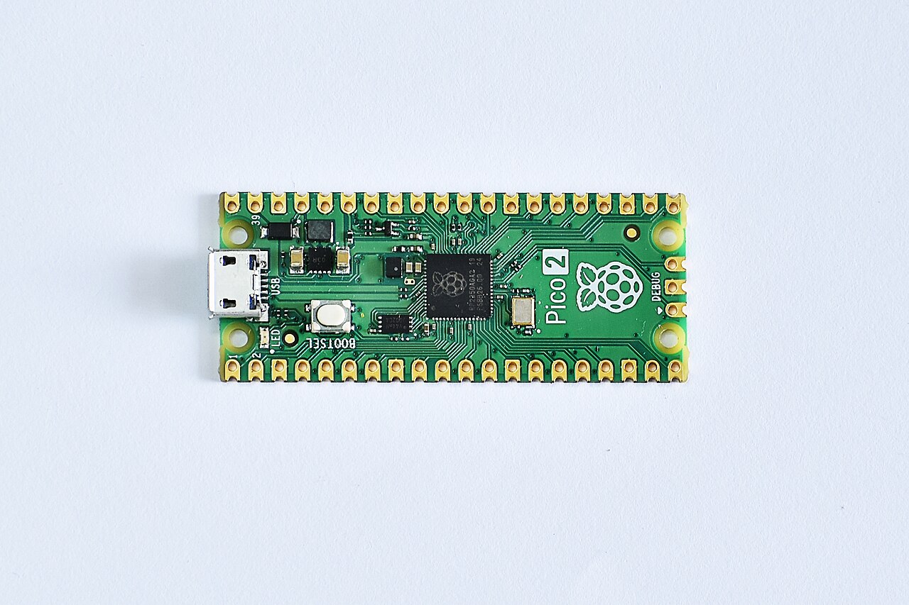
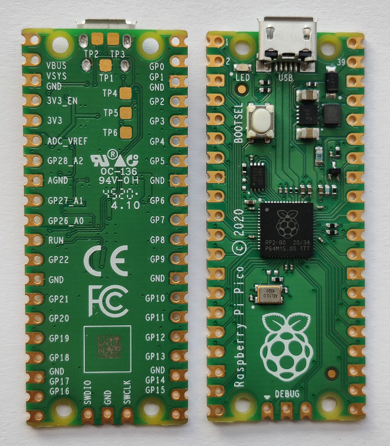
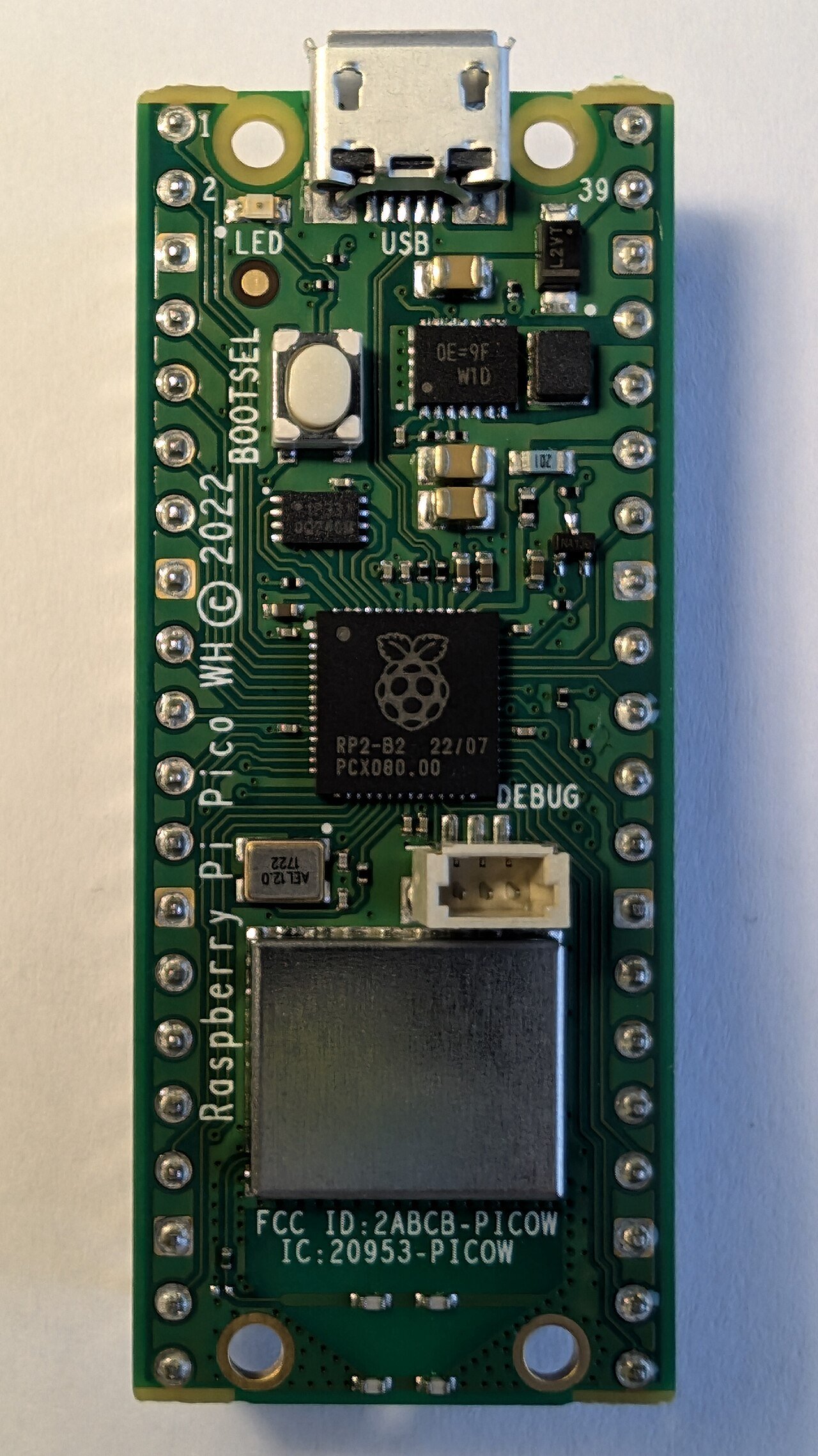
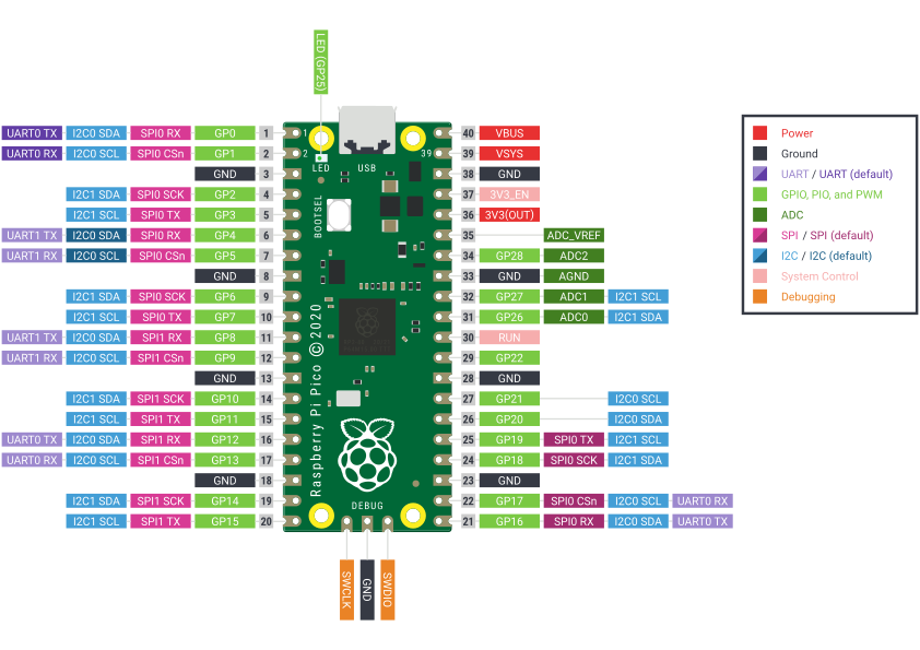
Pinout diagram
| Attr | Specs | verified |
|---|---|---|
mcu | Raspberry RP2040 — dual-core ARM Cortex-M0+ (ARMv6-M) @ 133 MHz nominal; "originally run at 133 MHz, but later certified at 200 MHz" (Wikipedia — RP2040; RP2040 datasheet). 40 nm TSMC process, 7×7 mm QFN-56 (Wikipedia). No FPU, no DSP on Cortex-M0+ (CircuitPython board page). | ✔ |
gpu | none (no video core; VGA can be bit-banged via PIO — see Features). | ? unverified |
ram | 264 KB SRAM on-chip in six independent banks, plus 16 KB of XIP cache usable as extra SRAM (RP2040 datasheet; errata E9 describes cache-as-SRAM). | ✔ |
storage | no internal flash; board carries a 2 MB external QSPI flash (Winbond W25Q16JV) with execute-in-place; RP2040 QSPI controller supports up to 16 MB (Pico datasheet §1, Wikipedia — RP2040). | ✔ |
connectivity | none wireless on this model (Wi-Fi/BT only on Pico W). Wired: USB 1.1 (LS/FS, device and host) controller + PHY (RP2040 datasheet key features). | ✔ |
gpio_board | 40-pin 0.1″ castellated DIP-style header exposing 26 of the RP2040's 30 GPIO, fixed at 3.3 V and not 5 V-tolerant ("All of the GPIO pins are 3.3V logic, and are not 5V-safe", CircuitPython board page; Pico datasheet §4.2). GP0–GP22 digital-only; GP26–GP28 digital/ADC. | ✔ |
peripherals_chip | 2 × UART, 2 × SPI, 2 × I²C, 16 PWM channels (8 slices × 2 channels), 4-channel 12-bit 500 ksps SAR ADC + 5th channel to on-chip temperature sensor, 12-channel DMA, 8 PIO state machines (2 blocks × 4), 1 timer with 4 alarms, RTC (RP2040 datasheet; PWM slice behaviour confirmed in MicroPython RP2 quick reference). No DAC (no true analog output, CircuitPython board page). | ✔ |
board_adc_specifics | on Pico only GP26–GP28 are broken out as ADC0–2; ADC3 is wired to VSYS/3 (battery monitoring) and ADC4 is the temperature sensor (Pico datasheet §4.3–4.4, MicroPython quickref). | ✔ |
power | micro-USB B (VBUS 5 V) → Schottky ORing diode → VSYS; on-board RT6150 buck-boost SMPS holds 3.3 V from ~1.8 V to 5.5 V on VSYS, so it runs from 1 Li-Ion cell or 3 AA cells; GPIO23 selects PFM/PWM regulator mode, GPIO24 senses VBUS, SMPS EN broken out on pin 37; 3.3 V available to external circuitry (Pico datasheet §4.4 Powerchain). | ✔ |
consumption_board_vbus_5_v_mean_of_3_boards | DORMANT ≈ 0.8 mA @25 °C (1.2–1.4 mA at −25/85 °C); SLEEP ≈ 1.3 mA @25 °C; the "Popcorn" VGA/SD/audio demo draws ≈ 86–93 mA (including the VGA daughter-board) (Pico datasheet §3.1). | ✔ |
temperature | electrical characterization performed at −25 / +25 / +85 °C (Pico datasheet §3.1 tables). | ✔ |
mechanical | single-sided 51 × 21 mm, 1 mm PCB, 40 × 0.1″ through-hole/castellated pins (reflow-solderable as a module), 4 × 2.1 mm mounting holes (Pico datasheet §2). | ✔ |
- Manufacturer: Raspberry Pi Ltd (UK). First microcontroller board from "Raspberry Silicon" — the company's own chip (Wikipedia — RP2040; launch blog "Meet Raspberry Silicon: Raspberry Pi Pico now on sale at $4", cited there).
- Year: launched 21 January 2021, together with the RP2040 chip (Wikipedia — RP2040; datasheet release history starts "21 January 2021", Pico datasheet).
- Status: Active. Raspberry Pi guarantees availability "until at least January 2028" (Pico datasheet, Appendix A).
- Price: launch and current RRP US$4.00 ("the Raspberry Pi Pico being introduced at US$4 and the RP2040 itself costing US$1", Wikipedia — RP2040; RRP table US$4.00, Pico datasheet, Appendix A.2). The header-soldered Pico H is listed at US$5.00 in the same table.
- Variants: Pico (unpopulated headers) / Pico H (pre-soldered headers); the wider Pico family adds Pico W (2022, adds Wi-Fi/Bluetooth via CYW43), Pico 2 and Pico 2 W (2024, RP2350 chip) (Wikipedia — RP2040 board table, Wikipedia — Raspberry Pi). The original Pico has no radio.
+ Strengths
- PIO (Programmable I/O): 2 blocks × 4 user-programmable state machines that "build low-level IO interfaces from scratch" and run without CPU time — NeoPixel streams, I2S audio, LED matrices, VGA, SD cards (CircuitPython board page, MicroPython quickref PIO example, Pico datasheet "Popcorn" VGA demo).
- Symmetric dual-core M0+ with hardware inter-core FIFOs and a fully-connected AHB crossbar — unusual at this price (RP2040 datasheet key features).
- 264 KB RAM — huge for a $4 MCU; plus 16 KB cache-as-SRAM trick (Wikipedia — RP2040, errata E9).
- Stateless design / flash density you choose: commodity QSPI flash from 512 KB to 16 MB, XIP with 16 KB cache (RP2040 datasheet).
- USB host capability on a $4 board (device + host, USB 1.1 PHY) (RP2040 datasheet).
- Flexible powerchain: 1.8–5.5 V VSYS buck-boost, selectable PFM/PWM regulator mode from GPIO, VBUS sensing pin, easy battery-charger integration (Pico datasheet §4.4–4.6).
- Fully open hardware: schematic, PCB layout, STEP and Fritzing files released "with no limitations" (Pico datasheet §1.1).
- UF2 ROM bootloader — recovery is impossible to brick from software mistakes in the boot path (Pico datasheet §4.1).
- Certified 200 MHz operation (vs 133 MHz nominal) on later silicon revisions (Wikipedia — RP2040).
− Weaknesses
- Silicon errata (RP2040 datasheet, Appendix B): E9 — ROM UF2 bootloader cannot boot directly into XIP cache-as-SRAM (bus fault; workaround: re-disable caching from SRAM); E14 — sparse/mis-aligned UF2 may not be written to flash correctly; E7/E10 — clock-generation errata; E12/E13 — DMA errata; E6/E11 — GPIO/ADC errata; E2/E3/E4 — USB errata (RP2040 datasheet, Appendix B, p. 627 ff.).
- ADC accuracy by design: no external reference pin — the ADC uses its RC-filtered 3.3 V supply, giving a ~30 mV inherent offset (≈150 µA × 200 Ω), SMPS ripple coupling, and chip-to-chip variation; documented fixes: ground-channel offset subtraction, forcing PWM regulator mode (GPIO23), or an external 3.0 V shunt reference on ADC_VREF (Pico datasheet §4.3).
- ADC pins GP26–GP29 have a reverse diode to IOVDD: input above ~3.6 V conducts, and applying voltage to them while the Pico is unpowered back-powers the 3V3 rail. Normal GP0–GP25 don't have this restriction (Pico datasheet §4.2).
- Not 5 V-tolerant anywhere — level-shift or use 3.3 V parts on every pin (CircuitPython board page).
- Flash-write vs XIP conflict: erasing/programming the QSPI flash stalls code fetches from it, which bites multicore and interrupt code; the SDK only gained a dedicated helper library (pico_flash, flash_safe_execute) in SDK 1.5.1 (2023) (pico-sdk 1.5.1 release notes).
- No FPU/DSP: all float math is software-emulated — "if you're doing something with heavy floating point math, it will be done in software" (CircuitPython board page).
- MicroPython RP2 quirk: after a hard reset, pins "operate in current sink mode at about 60 µA", which can skew ADC readings if pins aren't reconfigured (high-Z) first (MicroPython RP2 quickref, ADC section).
- Board sleep floor is ~1 mA, not µA: the datasheet's DORMANT/SLEEP figures (0.8–1.9 mA at VBUS) are dominated by the on-board SMPS and support circuitry; battery designs needing true µA standby must redesign the power supply or use the bare chip (Pico datasheet §3.1.3–3.1.4).
- USB is 1.1 only (12 Mbit/s full-speed): no high-speed, and USB-host current budget from a PC port is limited.
- Retour d'expérience expert expert — expert-raspberrypi
- Retour d'experience sur la Pico après plusieurs mois d'utilisation. Les points forts sont reels : le prix de 4 USD est imbattable pour un dual-core M0+ a 133 MHz (certifie 200 MHz sur les rev laterales) avec 264 KB de SRAM. La liberte materielle est totale, tout est open source. Cependant, attentio… — expert-raspberrypi
- Bonjour expert, je debute avec la Pico et je bute sur un souci d'alimentation. J'ai lu que les broches GP26 a GP28 ne sont pas 5V tolerantes, ce qui est logique, mais j'ai aussi vu dans la datasheet une note sur une diode inverse vers l'IOVDD. Est-ce que cela signifie que si j'applique une tension … — maker_tinker
- @maker_tinker Oui, c'est exactement ca. La datasheet est claire : appliquer une tension sur GP26-GP29 quand la Pico est hors tension peut back-powerrer le rail 3V3, ce qui est dangereux pour le MCU. Pour ton capteur 5V, utilise un diviseur de tension propre passe par des resis, mais assure-toi que … — pio_wizard
Community feedback and projects
- Je n'arrive pas à faire fonctionner la mémoire persistante sur mon raspberry pico forum.arduino.cc
- Raspberry Pi Pico not detected as USB drive in BOOTSEL mode forum.digikey.com
- Embedded Swift on the Raspberry Pi Pico forums.swift.org
- datasheets.raspberrypi.com/pico/pico-datasheet.pdf
- datasheets.raspberrypi.com/rp2040/rp2040-datasheet.pdf
- rptl.io/pico-get-started
- rptl.io/pico-c-sdk
- rptl.io/pico-doxygen
- raspberrypi.com/documentation/microcontrollers/pico-series.html
- MicroPython RP2 quickref
- raspberrypi/pico-sdk
- pico-examples
- pico-extras
- micropython.org/download
- circuitpython.org/board/raspberry_pi_pico
- Adafruit getting-started guide
- earlephilhower/arduino-pico guide
- github.com/rp-rs
- Wikipedia — RP2040
- Wikipedia — Raspberry Pi (Pico history)
- Silicon errata (RP2040 datasheet, Appendix B): E9 — ROM UF2 bootloader cannot boot directly into XIP cache-as-SRAM (bus fault; workaround: re-disable caching from SRAM); E14 — sparse/mis-aligned UF2 may not be written to flash correctly; E7/E10 — clock-generation errata; E12/E13 — DMA errata; E6/E11 — GPIO/ADC errata; E2/E3/E4 — USB errata (RP2040 datasheet, Appendix B, p. 627 ff.).
- ADC accuracy by design: no external reference pin — the ADC uses its RC-filtered 3.3 V supply, giving a ~30 mV inherent offset (≈150 µA × 200 Ω), SMPS ripple coupling, and chip-to-chip variation; documented fixes: ground-channel offset subtraction, forcing PWM regulator mode (GPIO23), or an external 3.0 V shunt reference on ADC_VREF (Pico datasheet §4.3).
- ADC pins GP26–GP29 have a reverse diode to IOVDD: input above ~3.6 V conducts, and applying voltage to them while the Pico is unpowered back-powers the 3V3 rail. Normal GP0–GP25 don't have this restriction (Pico datasheet §4.2).
- Not 5 V-tolerant anywhere — level-shift or use 3.3 V parts on every pin (CircuitPython board page).
- Flash-write vs XIP conflict: erasing/programming the QSPI flash stalls code fetches from it, which bites multicore and interrupt code; the SDK only gained a dedicated helper library (pico_flash, flash_safe_execute) in SDK 1.5.1 (2023) (pico-sdk 1.5.1 release notes).
- No FPU/DSP: all float math is software-emulated — "if you're doing something with heavy floating point math, it will be done in software" (CircuitPython board page).
- MicroPython RP2 quirk: after a hard reset, pins "operate in current sink mode at about 60 µA", which can skew ADC readings if pins aren't reconfigured (high-Z) first (MicroPython RP2 quickref, ADC section).
- Board sleep floor is ~1 mA, not µA: the datasheet's DORMANT/SLEEP figures (0.8–1.9 mA at VBUS) are dominated by the on-board SMPS and support circuitry; battery designs needing true µA standby must redesign the power supply or use the bare chip (Pico datasheet §3.1.3–3.1.4).
- USB is 1.1 only (12 Mbit/s full-speed): no high-speed, and USB-host current budget from a PC port is limited.
- Faire clignoter la LED embarquée (GP25) debutant Schéma : IMG-pico-debutant-1-pico-blink-led.svg — Raspberry Pi Pico vue de dessus avec la LED embarquée GP25 mise en évidence et le câble micro-USB branché
- Lire un bouton poussoir et gérer le rebond debutant Schéma : IMG-pico-debutant-2-pico-bouton-gpio.svg — Pico avec un bouton poussoir câblé entre GP2 et GND, résistance de pull-up interne représentée sur la puce
- Lire un potentiomètre avec l'ADC 12 bits debutant Schéma : IMG-pico-debutant-3-pico-adc-potentiometre.svg — potentiomètre relié à 3V3, GND et GP26 (ADC0) de la Pico, tension USB et console série affichant les valeurs
- Piloter un micro-servo avec le PWM intermediaire Schéma : IMG-pico-intermediaire-1-pico-pwm-servo.svg — micro-servo SG90 alimenté par une source externe 5 V, signal sur GP1 de la Pico, masses reliées, angles 0/90/180 degrés annotés
- Première machine à états PIO : un blink sans CPU intermediaire Schéma : IMG-pico-intermediaire-2-pico-pio-machine-etats.svg — bloc PIO du RP2040 avec une machine à états (SM0) et sa boucle d'états set/delay/jmp, sortie reliée à GP25, cœur CPU endormi à côté
- Installer MicroPython et écrire main.py intermediaire Schéma : IMG-pico-intermediaire-3-pico-micropython.svg — Pico en mode BOOTSEL apparaissant comme lecteur RPI-RP2, fichier firmware uf2 déposé dessus, puis fenêtre REPL série
- Exploiter les deux cœurs M0+ avec les FIFO inter-cœurs avance Schéma : IMG-pico-avance-1-pico-double-coeur.svg — RP2040 avec les deux cœurs Cortex-M0+ côte à côte reliés par une file FIFO matérielle et une ligne d'interruption inter-cœur, mémoires partagées en dessous
- Boot UF2, BOOTSEL et récupération d'une carte « briquée » avance Schéma : IMG-pico-avance-2-pico-boot-uf2-recovery.svg — cycle de boot du RP2040 : broche BOOTSEL, bootrom en ROM, choix flash QSPI externe ou USB, lecteur RPI-RP2 et fichier uf2 déposé
- Sommeil profond, dormclock et PIO autonome sur batterie avance Schéma : IMG-pico-avance-3-pico-sommeil-pio.svg — Pico sur cellule Li-Ion reliée à VSYS, cœur CPU endormi (WFI), réveil par GPIO et alarme du timer, machine PIO toujours active, courants dormant et sleep annotés
Code library — examples written for this board
clignotante.pyPythonbouton-interruption.pyPythonpwm-servo.pyPythonlecture-adc.pyPythonneopixel.pyPythonoled-i2c.pyPythoncapteur-dht.pyPythonjournalisation.pyPythonuart-commandes.pyPythontaches-cooperatives.pyPython
Examples and repos found online
- raspberrypi/pico-examples github.com
- raspberrypi/pico-sdk github.com
- raspberrypi/pico-micropython-examples github.com
- pimoroni/pimoroni-pico github.com
- raspberrypi/pico-playground github.com