STM32F4DISCOVERY (STM32F407VGT6 Discovery kit)
⚡ The essentials in 60 seconds
- cpu — ARM Cortex-M4 (single core), FPU (single-precision), up to 168 MHz, ~210 DMIPS class (F4 series is ST's "high-performance" Cortex-M4F line per Wikipedia STM32 series table).
- memory — 1 MB (1024 KB) flash; 192 KB SRAM including 64 KB core-coupled memory (CCM) plus 4 KB battery-backed RAM (Zephyr: "192+4 KB SRAM including 64-Kbyte of core coupled memory"; Wikipedia board entry: "1024 KB flash, 192 KB RAM, 4 KB battery-backed").
- gpu — none (2D-only DMA2D Chrom-GFX ART accelerator on some F4 parts; the F407 has the ART accelerator, no GPU, no display controller on this board).
- on_chip_peripherals_f407_per_zephyr_board_doc_feature_list — 3× 12-bit ADC (24 channels), 2× 12-bit DAC, RTC, advanced-control timer + 17 general-purpose timers, 2× watchdog, 6× USART/UART, 3× I2C, 3× SPI, SDIO, 2× CAN, USB 2.0 OTG FS (on-chip PHY), USB 2.0 OTG HS/FS with DMA + full-speed PHY + ULPI, 10/100 Ethernet MAC (MAC only — no PHY/RMII connector is fitted on this board), 8- to 14-bit parallel camera interface, CRC unit, true RNG, DMA controllers.
- gpio_expansion — LQFP100 package; two extension headers expose essentially all LQFP100 I/Os ("Extension header for all LQFP100 I/Os", Zephyr). Arduino core variant exposes 79 digital pins, 16 analog inputs for this board (variant_DISCO_F407VG.h). I/O voltage: VDD 1.8–3.6 V (Zephyr); GPIOs are 3.3 V, 5 V-tolerant on most pins per the F407 datasheet.
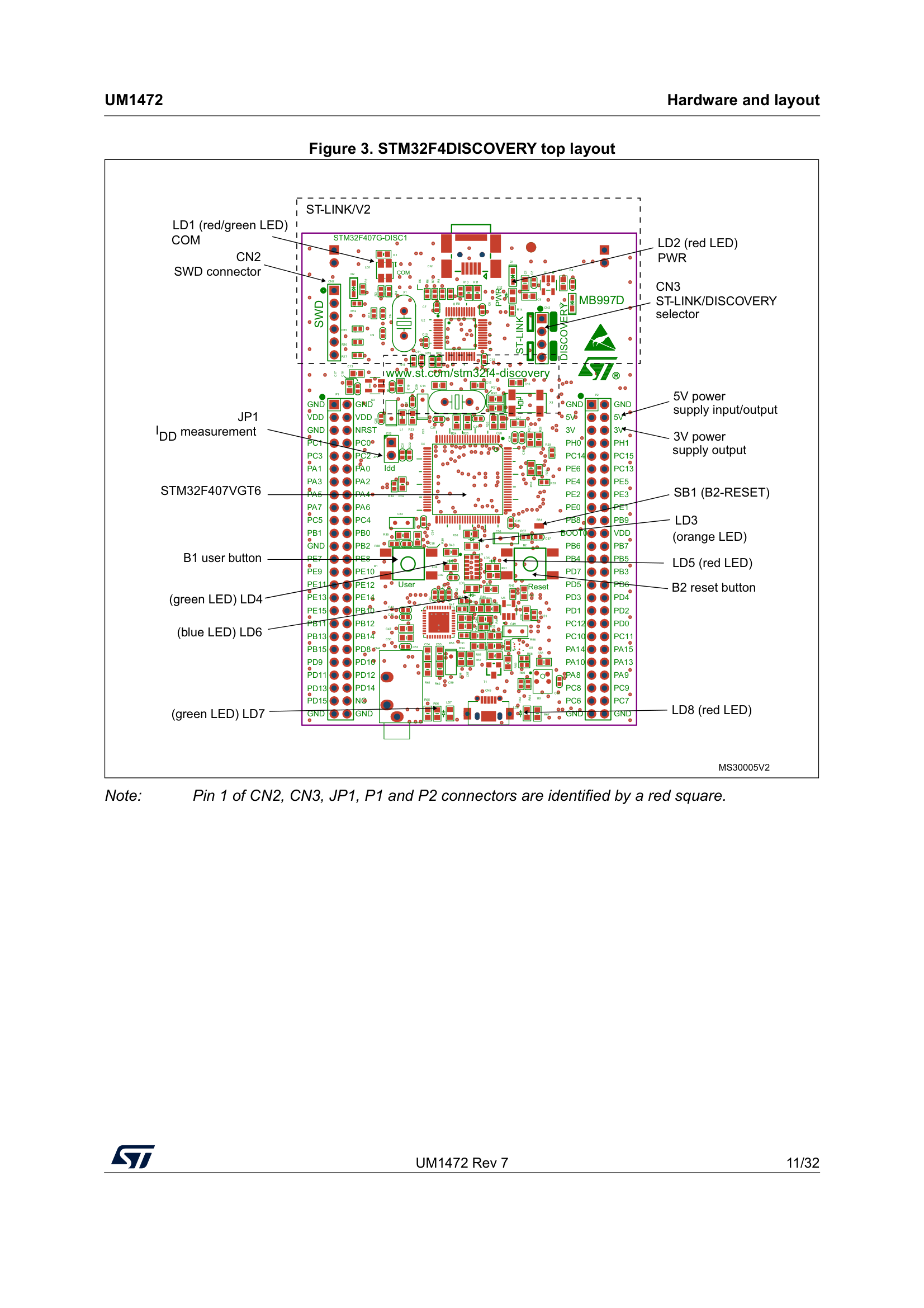
- on_board_i_o — - 4 user LEDs on PD12–PD15: green (LD4/PD12), orange (LD3/PD13), red (LD5/PD14), blue (LD6/PD15) — pin map from ST BSP stm32f4_discovery.h (LED4=PD12, LED3=PD13, LED5=PD14, LED6=PD15); colors cross-checked between Zephyr doc and MicroPython STM32F4DISC/mpconfigboard.h. Plus LD1 (USB), LD2 (3.3 V PWR), LD7/LD8 (OTG VBUS/over-current) — 8 LEDs total (Zephyr). - Buttons: USER (PA0, also WKUP) and RESET (Zephyr; ST BSP KEY_BUTTON_PIN = GPIO_PIN_0 / GPIOA). There is no joystick on this board (that's other Discovery kits). - Audio: CS43L22 audio DAC with integrated class D speaker driver (ST product page; BSP checks CS43L22_ID on I2C1, device address 0x94, reset pin PD4) + MP45DT02 omni-directional PDM digital microphone (Zephyr; BSP records via I2S2 + PDM filter), headphone jack, speaker connector. - MEMS: LIS302DL or LIS3DSH 3-axis accelerometer on SPI1 (SCK PA5 / MISO PA6 / MOSI PA7, CS PE3, INT PE0/PE1) — ST BSP stm32f4_discovery_accelerometer.c.
- On this board : 9 tutorials · 10 code
When you look at the landscape of embedded electronics development boards, few have left as lasting an imprint as the STM32F4DISCOVERY. Launched by STMicroelectronics in early 2012, shortly after the announcement of the STM32F4 series in September 2011, this board was designed to be a gateway into high-performance microcontroller programming. At its heart sits the STM32F407VGT6, a microcontroller unit (MCU) that represents a significant leap in capability for its time. To understand why this board matters, one must first understand the "brain" inside it. The F407 is based on the ARM Cortex-M4 architecture, a design that balances power efficiency with computational speed. Specifically, it runs at up to 168 MHz, which means its internal clock ticks 168 million times per second, allowing it to process instructions rapidly. Crucially, this processor includes a Floating-Point Unit (FPU). In simpler terms, while many basic microcontrollers struggle with decimal calculations, the FPU allows the F407 to handle complex math, such as audio processing or sensor fusion, with remarkable speed and accuracy. This combination made it a flagship for ST’s "high-performance" line, offering around 210 DMIPS (Dhrystone Million Instructions Per Second), a standard benchmark for raw processing power.
The board’s memory configuration is equally impressive for an embedded system. It features 1024 KB (1 MB) of Flash memory, where your program code is stored permanently, and 192 KB of SRAM (Static Random Access Memory) for temporary data handling. A unique feature of this chip is the inclusion of 64 KB of Core-Coupled Memory (CCM), a specialized fast memory directly connected to the processor core, which significantly speeds up data access for critical tasks. Additionally, there are 4 KB of battery-backed RAM, which retains data even when the main power is cut, provided a backup battery is connected. While the board does not include a Graphics Processing Unit (GPU) or a display controller, it does feature an ART (Adaptive Real-Time) accelerator, which helps the processor fetch instructions from Flash memory more efficiently, preventing bottlenecks during high-speed execution.
What truly distinguished the STM32F4DISCOVERY from its peers was its focus on audio applications. ST explicitly marketed it as a tool to "develop audio applications easily," and the hardware reflects this priority. The board integrates a CS43L22 audio Digital-to-Analog Converter (DAC) with an integrated Class D speaker driver. A Class D amplifier is highly efficient, converting digital audio signals into analog sound with minimal heat generation, making it ideal for battery-powered or compact devices. For input, the board includes an MP45DT02 omnidirectional PDM (Pulse Density Modulation) digital microphone. PDM is a method of encoding audio signals that is robust against noise and simple to process digitally. With a headphone jack and a speaker connector also present, the board allows developers to record, process, and play back audio without needing external components. This audio-first approach made it a favorite for projects involving voice recognition, music synthesis, or simple audio effects.
Beyond audio, the board is equipped with a 3-axis MEMS (Micro-Electro-Mechanical Systems) accelerometer. It is important to note that the specific model of this sensor varies by board revision; early boards used the LIS302DL, while later versions switched to the LIS3DSH. Both are connected via the SPI (Serial Peripheral Interface) bus, a high-speed communication protocol. The accelerometer allows the board to detect motion, tilt, and even "clicks" or taps, enabling interactive projects that respond to physical movement. For user interaction, there are four user-controllable LEDs (green, orange, red, and blue) and a single USER button. These simple outputs and inputs are essential for debugging and basic interaction, allowing developers to visually confirm that their code is running as expected.
Connectivity is another strong suit. The board features two distinct USB ports. One is dedicated to the on-board ST-LINK/V2-A debugger and programmer. This is a critical feature for beginners and professionals alike, as it allows you to write code to the microcontroller and debug it in real-time without needing to buy a separate, expensive hardware probe. The second USB port is a full OTG (On-The-Go) Full Speed interface, which allows the board to act as a USB device (like a keyboard or storage drive) or even a host (to connect other USB devices), though it requires specific software configuration. The board also exposes a vast array of communication protocols on its expansion headers, including two CAN buses (common in automotive applications), an Ethernet MAC (though no physical Ethernet port is fitted, requiring an external PHY chip), SDIO for SD cards, and multiple UARTs, I2C, and SPI interfaces. This richness makes it a versatile platform for connecting to a wide variety of sensors and peripherals.
However, potential users should be aware of several nuances and limitations. The board is officially marked as obsolete or end-of-life by STMicroelectronics, having been superseded by the Nucleo series and newer Discovery kits. Despite this, it remains widely available on the second-hand market and is fully supported by major software ecosystems like STM32CubeF4, Zephyr RTOS, Arduino (via STM32duino), MicroPython, and Rust. One common point of confusion involves the serial console. On many revisions, the virtual COM port provided by the ST-LINK is not automatically wired to the microcontroller’s serial pins. Users often need to manually connect jumpers or use a separate USB-to-serial adapter connected to specific pins (like PA2/PA3) to see text output from their code. Additionally, because the accelerometer chip changed over time, code must be written to auto-detect which version is present, or it may fail to read sensor data. The board also lacks a joystick, which is present on some other Discovery kits, and the audio codec can be sensitive to interrupt handling, potentially causing audio glitches if not programmed carefully.
Despite these caveats, the STM32F4DISCOVERY remains a powerful educational and prototyping tool. Its blend of processing power, specialized audio hardware, and extensive connectivity options offers a comprehensive introduction to embedded systems. Whether you are learning to blink an LED, processing audio in real-time, or interfacing with complex sensors, the board provides a robust and well-documented platform. Its legacy is evident in the vast amount of community tutorials, open-source libraries, and example projects available online, making it a resilient choice for hobbyists and engineers who value a mature ecosystem and a proven hardware design.
Pinout diagram
| Attr | Specs | verified |
|---|---|---|
cpu | ARM Cortex-M4 (single core), FPU (single-precision), up to 168 MHz, ~210 DMIPS class (F4 series is ST's "high-performance" Cortex-M4F line per Wikipedia STM32 series table). | ? unverified |
memory | 1 MB (1024 KB) flash; 192 KB SRAM including 64 KB core-coupled memory (CCM) plus 4 KB battery-backed RAM (Zephyr: "192+4 KB SRAM including 64-Kbyte of core coupled memory"; Wikipedia board entry: "1024 KB flash, 192 KB RAM, 4 KB battery-backed"). | ? unverified |
gpu | none (2D-only DMA2D Chrom-GFX ART accelerator on some F4 parts; the F407 has the ART accelerator, no GPU, no display controller on this board). | ? unverified |
on_chip_peripherals_f407_per_zephyr_board_doc_feature_list | 3× 12-bit ADC (24 channels), 2× 12-bit DAC, RTC, advanced-control timer + 17 general-purpose timers, 2× watchdog, 6× USART/UART, 3× I2C, 3× SPI, SDIO, 2× CAN, USB 2.0 OTG FS (on-chip PHY), USB 2.0 OTG HS/FS with DMA + full-speed PHY + ULPI, 10/100 Ethernet MAC (MAC only — no PHY/RMII connector is fitted on this board), 8- to 14-bit parallel camera interface, CRC unit, true RNG, DMA controllers. | ? unverified |
gpio_expansion | LQFP100 package; two extension headers expose essentially all LQFP100 I/Os ("Extension header for all LQFP100 I/Os", Zephyr). Arduino core variant exposes 79 digital pins, 16 analog inputs for this board (variant_DISCO_F407VG.h). I/O voltage: VDD 1.8–3.6 V (Zephyr); GPIOs are 3.3 V, 5 V-tolerant on most pins per the F407 datasheet. | ? unverified |
on_board_i_o | - 4 user LEDs on PD12–PD15: green (LD4/PD12), orange (LD3/PD13), red (LD5/PD14), blue (LD6/PD15) — pin map from ST BSP stm32f4_discovery.h (LED4=PD12, LED3=PD13, LED5=PD14, LED6=PD15); colors cross-checked between Zephyr doc and MicroPython STM32F4DISC/mpconfigboard.h. Plus LD1 (USB), LD2 (3.3 V PWR), LD7/LD8 (OTG VBUS/over-current) — 8 LEDs total (Zephyr). - Buttons: USER (PA0, also WKUP) and RESET (Zephyr; ST BSP KEY_BUTTON_PIN = GPIO_PIN_0 / GPIOA). There is no joystick on this board (that's other Discovery kits). - Audio: CS43L22 audio DAC with integrated class D speaker driver (ST product page; BSP checks CS43L22_ID on I2C1, device address 0x94, reset pin PD4) + MP45DT02 omni-directional PDM digital microphone (Zephyr; BSP records via I2S2 + PDM filter), headphone jack, speaker connector. - MEMS: LIS302DL or LIS3DSH 3-axis accelerometer on SPI1 (SCK PA5 / MISO PA6 / MOSI PA7, CS PE3, INT PE0/PE1) — ST BSP stm32f4_discovery_accelerometer.c. | ? unverified |
usb | ST-LINK/V2-A debugger connector + USB OTG FS micro-AB connector (ST product page: "USB OTG Micro-AB connector"; Zephyr: "USB OTG FS with micro-AB connector"; OTG FS pins PA11/PA12, VBUS detect PA9, ID PA10 per MicroPython/Arduino variant files). | ? unverified |
power | flexible supply — USB VBUS or external 3.3 V / 5 V / 7–12 V, with power-management access point (Zephyr board doc). | ? unverified |
typical_consumption_temperature | ? unverified |
- Manufacturer: STMicroelectronics.
- Product: STM32F4DISCOVERY high-performance evaluation/discovery board, described by ST as leveraging "the capabilities of the STM32F407 high-performance microcontrollers, to allow users to develop audio applications easily" (ST product page, fetched 2026-10-13).
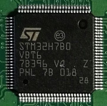
- MCU on board: STM32F407VGT6, ARM Cortex-M4F @ 168 MHz, 1024 KB flash, 192 KB RAM + 4 KB battery-backed RAM, LQFP100 (Wikipedia "STM32", Discovery boards section; Zephyr board docs).
- Launch: the STM32F4 series (Cortex-M4F) was announced by ST in September 2011 (Wikipedia STM32 history table); the F4DISCOVERY board itself shipped shortly after, in early 2012.
- Status: obsolete / end-of-life. Wikipedia's Discovery boards section explicitly labels the STM32F4DISCOVERY board "(obsolete)" (fetched 2026-10-13); the ST product page is still online but the board has been superseded by Nucleo-F4xx boards and newer Discovery kits. It remains widely available on the second-hand market and is still fully supported by CubeF4, Zephyr, stm32duino, MicroPython and OpenOCD.
- Variants / board revisions: several hardware revisions existed over the product life; the on-board MEMS accelerometer differs by revision (LIS302DL on early boards, LIS3DSH on later ones — ST's BSP auto-detects both by reading the chip ID, see stm32f4discovery-bsp). The current ST product page describes "one MEMS digital accelerometer" (singular).
- Related boards in the same family: STM32F401CDISCOVERY (F401VC), STM32F411E-DISCOVERY, STM32F412G-DISCOVERY, STM32F413H-DISCOVERY, STM32F429I-DISCOVERY, STM32F469I-DISCOVERY (all listed in the STM32CubeF4 README board list). Note: the LSM330 6-axis IMU some sources associate with "F4 Discovery" is on the F401/F411 Discovery kits, not on the original STM32F4DISCOVERY.
+ Strengths
- Audio-first Discovery: CS43L22 DAC + class-D speaker driver + MP45DT02 PDM mic + headphone jack on a sub-$20-class board — ST's pitch was "develop audio applications easily" (ST product page). Full record/play BSP with I2S3 (playback) / I2S2 (PDM capture) in CubeF4.
- On-board ST-LINK/V2-A debugger/programmer with SWD connector — zero external probe needed (ST product page; Zephyr).
- Cortex-M4F @ 168 MHz with FPU + DSP instructions was the performance flagship of ST's M4 line; 1 MB flash made it a long-lived teaching/hackathon board.
- MEMS accelerometer with click/tap interrupt (LIS302DL/LIS3DSH on SPI1, INT on PE0/PE1) — used in ST's "Accelerometer" demos.
- Dual USB: dedicated ST-LINK port plus a real USB OTG FS device/host micro-AB port (device class demos, host mass-storage, etc.).
- Rich silicon exposed on headers: CAN ×2, Ethernet MAC (chip-level), camera parallel interface, SDIO, DAC ×2 — useful for breakout experiments even though the board exposes no PHY/SD socket/jack for them.
- Ecosystem density: first-party BSP + examples in CubeF4, Zephyr, mbed (legacy), Arduino core, MicroPython, libopencm3-style OpenOCD configs — arguably the most software-supported dev board of the 2012 decade.
− Weaknesses
- ST-LINK VCP is not wired to the MCU's USART on stock boards. Zephyr board doc: "Please note that ST-Link Virtual Com Port is not wired to chip serial port. In order to enable console output you should use a serial cable and connect it to UART2 pins (PA2/PA3)." Note the contradiction: the Arduino core's variant_DISCO_F407VG.h labels USART2 (PA2/PA3) as "Connected to ST-Link" — on many board revisions the VCP-to-USART2 jumpers (CN3/CN5 area) must be checked/enabled, and some revisions simply lack the wiring. Verify on your specific revision before relying on Serial over the ST-LINK USB port.
- Accelerometer part varies by board revision (LIS302DL vs LIS3DSH, both on SPI1). Code must auto-detect via chip ID like ST's BSP does, or read the marking; naive single-driver code silently fails on the other revision. (ST BSP stm32f4_discovery_accelerometer.c.)
- UART1 is unusable without board modification: its alternate pins are PB6/PB7, and PB6 is tied to the audio codec I2C SCL (MicroPython mpconfigboard.h comment: "Without board modifications, this makes UART1 unusable on this board").
- PA0 conflicts: the USER button shares PA0 with UART4 TX/CTS and WKUP; MicroPython notes removing SB20 (back of board) to free PA0.
- Speaker noise at low sample rates: ST BSP "Known Limitations": low-quality audio files "may produce high and uncomfortable noise level" on the class-D speaker; raise sampling rate >48 kHz.
- I2C codec corruption risk: ST BSP limitation — I2C communication with the CS43L22 "may be corrupted if it is interrupted by some user interrupt routines".
- Audio driver constraints: BSP supports stereo 16-bit streams only (mono must be duplicated) — ST BSP limitations 4 & 5.
- Board is obsolete/EOL (Wikipedia label): no revisions, no supply guarantee; errata for the F407 silicon (ES0209 or later revision documents) apply — check the current errara sheet for the die revision you get.
- PC7 caution: connected to the codec MCLK input; using it as UART output only makes sense when the codec is unused (MicroPython comment).
- Retour d'expérience expert expert — expert-microcontroleur
- J'ai enfin pris le temps de creuser cette carte. Sur le papier, c'est un monstre pour l'audio avec le CS43L22 et le micro PDM, et l'argument d'être sous les 20 dollars pour du F407 a 168MHz est difficile a battre. Le BSP CubeF4 pour la lecture/enregistrement est complet. Par contre, attention au pi… — expert-microcontroleur
- Merci pour ce retour ! C'est exactement le problème que j'ai rencontre la semaine derniere. Je pensais que le ST-LINK etait magiquement relie au port série, donc j'ai passe une soiree a vérifier ma config GPIO sans rien comprendre. Du coup, jai du souder deux fils pour relier le TX/RX de l'adaptate… — maker_du_samedi
- Pour repondre a ta question sur la simultaneite I2S, en theorie le F407 gere très bien les deux canaux independants, mais la configuration DMA doit être faite avec soin pour ne pas saturer le bus AHB. Concernant le problème du VCP, c'est dommage que ST ne l'ait pas cable sur cette revision par defa… — codeur_embedde
Community feedback and projects
- STM32F4-Discovery board review wej.k.vu
- STM32F4 Discovery + Mac OS X + GCC + OpenOCD + Eclipse electronics.stackexchange.com
- USB-MIDI Interface with STM32F4 Discovery? electronics.stackexchange.com
- STM32F4 Discovery board for ethernet development community.st.com
Content not available yet.
- ST-LINK VCP is not wired to the MCU's USART on stock boards. Zephyr board doc: "Please note that ST-Link Virtual Com Port is not wired to chip serial port. In order to enable console output you should use a serial cable and connect it to UART2 pins (PA2/PA3)." Note the contradiction: the Arduino core's variant_DISCO_F407VG.h labels USART2 (PA2/PA3) as "Connected to ST-Link" — on many board revisions the VCP-to-USART2 jumpers (CN3/CN5 area) must be checked/enabled, and some revisions simply lack the wiring. Verify on your specific revision before relying on Serial over the ST-LINK USB port.
- Accelerometer part varies by board revision (LIS302DL vs LIS3DSH, both on SPI1). Code must auto-detect via chip ID like ST's BSP does, or read the marking; naive single-driver code silently fails on the other revision. (ST BSP stm32f4_discovery_accelerometer.c.)
- UART1 is unusable without board modification: its alternate pins are PB6/PB7, and PB6 is tied to the audio codec I2C SCL (MicroPython mpconfigboard.h comment: "Without board modifications, this makes UART1 unusable on this board").
- PA0 conflicts: the USER button shares PA0 with UART4 TX/CTS and WKUP; MicroPython notes removing SB20 (back of board) to free PA0.
- Speaker noise at low sample rates: ST BSP "Known Limitations": low-quality audio files "may produce high and uncomfortable noise level" on the class-D speaker; raise sampling rate >48 kHz.
- I2C codec corruption risk: ST BSP limitation — I2C communication with the CS43L22 "may be corrupted if it is interrupted by some user interrupt routines".
- Audio driver constraints: BSP supports stereo 16-bit streams only (mono must be duplicated) — ST BSP limitations 4 & 5.
- Board is obsolete/EOL (Wikipedia label): no revisions, no supply guarantee; errata for the F407 silicon (ES0209 or later revision documents) apply — check the current errara sheet for the die revision you get.
- PC7 caution: connected to the codec MCLK input; using it as UART output only makes sense when the codec is unused (MicroPython comment).
- Premier téléversement sur la STM32F4DISCOVERY avec l'Arduino STM32duino debutant Schéma : STM32F4DISCOVERY vue de dessus avec les quatre LED utilisateur (verte PD12, orange PD13, rouge PD14, bleue PD15), le bouton USER sur PA0 et les deux ports micro-USB (ST-LINK à gauche, OTG FS à droite) ; à côté, l'Arduino IDE avec la carte STM32F407G-DISC1 sélectionnée.
- Zephyr RTOS sur la STM32F4DISCOVERY : west build et west flash debutant Schéma : flux de compilation Zephyr pour la carte stm32f4_disco — ligne de commande west build, fichier .elf produit, puis west flash via le ST-LINK/V2-A intégré ; la LED LD4 verte (PD12) clignote sur la carte.
- MicroPython sur la STM32F4DISCOVERY : REPL interactif et pilotage des LED debutant Schéma : la STM32F4DISCOVERY reliée par son port micro-USB OTG FS à un ordinateur ; sur l'écran, une fenêtre de REPL MicroPython affichant le prompt >>> et la commande led.on() ; les quatre LED PD12 à PD15 sont annotées.
- STM32Cube HAL et BSP officiel : LED, bouton et accéléromètre avec détection automatique intermediaire Schéma : arborescence du paquet STM32CubeF4 mise en évidence — Drivers/BSP/STM32F4-Discovery, Drivers/BSP/Components (lis302dl, lis3dsh) et Projects/STM32F4-Discovery — avec la carte STM32F4DISCOVERY et sa puce accéléromètre reliée au bus SPI1 (PA5/PA6/PA7, CS PE3).
- Lecture audio sur le codec CS43L22 : I2S, classe D et les limitations du BSP intermediaire Schéma : chaîne audio de la STM32F4DISCOVERY — MCU STM32F407 sortant en I2S3 vers le codec CS43L22 (DAC + ampli classe D), piloté en I2C1 (adresse 0x94, reset PD4), avec sortie casque et connecteur haut-parleur ; encart sur les limitations : stéréo 16 bits uniquement, bruit sous 48 kHz.
- USB OTG FS sur le port micro-AB : se faire passer pour un périphérique classe CDC intermediaire Schéma : les deux mondes USB de la STM32F4DISCOVERY — à gauche le port ST-LINK/V2-A (programmation), à droite le connecteur micro-AB OTG FS (PA11/PA12, VBUS PA9, ID PA10) reliant la carte à un PC qui voit un port série CDC ; les LED LD7/LD8 signalent VBUS et surintensité.
- Acquérir le micro PDM MP45DT02 : I2S2, filtre PDM-vers-PCM et contraintes de sortie avance Schéma : chaîne d'acquisition micro de la STM32F4DISCOVERY — micro omnidirectionnel MP45DT02 en sortie PDM 1 bit horlogée par I2S2, décimation logicielle vers un PCM 16 bits, puis exfiltration vers un PC via un convertisseur USB-série externe sur UART2 (PA2/PA3) ; encart : UART1 interdit (PB6 = SCL du codec), PA0 occupé par USER.
- Rust embarqué et OpenOCD sur la Discovery F4 : chaîne complète sans CubeIDE avance Schéma : chaîne de développement bare-metal de la STM32F4DISCOVERY — éditeur Rust (stm32f4xx-hal), compilateur cross thumbv7em, GDB pilotant OpenOCD (stm32f4discovery.cfg, ST-LINK, SWD) relié au STM32F407 ; en arrière-plan, la carte mémoire : flash 1024 Ko, SRAM 192 Ko dont 64 Ko CCM, 4 Ko sauvegardée.
- Réveil sur claquement : interruption click du MEMS, double révision et EXTI sur PE0/PE1 avance Schéma : l'accéléromètre MEMS de la STM32F4DISCOVERY en SPI1 (SCK PA5, MISO PA6, MOSI PA7, CS PE3) avec ses deux broches d'interruption INT1/INT2 reliées à PE0/PE1 configurées en EXTI ; un bloc « chip ID » arbitre entre LIS302DL (révision ancienne) et LIS3DSH (révision récente) ; la LED rouge PD14 s'allume sur détection de claquement.
Code library — examples written for this board
clignotante.cCbouton-hal.cCusart-printf.cCadc-temperature.cCpwm-timer-led.cCservo-pwm.cCi2c-oled.cCwatchdog-iwdg.cCrtc-reveil.cCusart-reception.cC
Examples and repos found online
- STMicroelectronics/STM32CubeF4 github.com
- stm32duino/Arduino_Core_STM32 github.com
- zephyrproject-rtos/zephyr github.com