Arduino UNO R4 WiFi
⚡ The essentials in 60 seconds
- main_mcu — Renesas RA4M1 (Arm Cortex-M4) @ 48 MHz, 32 KB SRAM, 256 KB flash; RTC, 12-bit DAC, CAN bus, USB HID (docs page).
- co_processor — Espressif ESP32-S3 module for Wi-Fi (2.4 GHz) / Bluetooth®, "which can also be separately programmed via a specific header" (docs page). Module family: ESP32-S3-MINI (Espressif ESP32-S3 datasheet).
- gpio — 14 digital I/O + 6 analog inputs at 5 V ("The RA4M1 and the GPIOs of this board operates on 5 V", docs page); ADC up to 14-bit, DAC 12-bit (docs — R4 family).
- onboard_extras — 12×8 red LED matrix, Qwiic (JST) I²C connector, VRTC backup pin, OFF pin (store page), USB-C, SWD debug, op-amp (store page for the shared R4 feature set).
- power — VIN or barrel jack 6–24 V (docs page).
- current_limit — 8 ma
- On this board : 9 tutorials · 10 code
The Arduino UNO R4 WiFi represents a significant evolution in the iconic UNO line, released in June 2023 as a dual-microcontroller board that bridges the gap between traditional embedded control and modern connectivity. Unlike its predecessors, which relied on a single chip, this board features two distinct processing units working in tandem. The primary brain is the Renesas RA4M1, an Arm Cortex-M4 microcontroller running at 48 MHz. To put this in perspective, frequency refers to the number of cycles the processor can execute per second; at 48 million cycles, this chip is significantly faster than the older AVR chips found in previous UNO models, allowing for more complex calculations and smoother real-time operations. It comes equipped with 32 KB of SRAM, which is the fast, temporary memory used for running programs, and 256 KB of flash storage, where your code is permanently saved. This main processor handles the core logic, input/output operations, and the board’s unique peripherals, operating on a 5-volt logic level, which ensures compatibility with the vast ecosystem of existing UNO shields and components.
Complementing the main processor is a co-processor module from Espressif, the ESP32-S3-MINI. This chip is responsible for wireless communication, specifically Wi-Fi on the 2.4 GHz band and Bluetooth. In technical terms, a co-processor is a secondary processor that offloads specific tasks from the main CPU; here, it handles the heavy lifting of radio signals and network protocols, allowing the main RA4M1 to focus on your application logic. A unique feature of this architecture is that the ESP32-S3 is not just a passive radio module; it can be programmed independently via a dedicated header, enabling developers to use the extensive ESP32 ecosystem if desired. However, for most users, it operates under the control of the main Arduino core, exposing Wi-Fi and Bluetooth capabilities through standard Arduino libraries. This dual-chip setup introduces some complexity, particularly regarding voltage levels. While the main GPIO pins operate at 5 volts, the ESP32-S3 section and its specific header are strictly 3.3-volt devices. Connecting 5-volt signals to these pins can damage the board, so users must be mindful of this distinction when wiring external components to the ESP header.
The board’s physical interface remains familiar to long-time Arduino users, featuring 14 digital input/output pins and 6 analog inputs. However, a critical specification to note is the current limit per pin, which is capped at 8 milliamperes. This is a tighter budget compared to older AVR-based UNOs, meaning that driving high-current devices directly from a GPIO pin might exceed this limit and potentially harm the pin or the board. For power management, the UNO R4 WiFi accepts an input voltage between 6 and 24 volts via the VIN pin or barrel jack, offering flexibility for various power sources. It also includes a USB-C port for programming and power, replacing the older USB-B connector. The board supports USB HID (Human Interface Device) functionality, allowing it to act as a keyboard or mouse, and includes a CAN bus interface for industrial communication protocols. An onboard operational amplifier and a 12-bit DAC (Digital-to-Analog Converter) provide higher resolution analog output capabilities, while the ADC (Analog-to-Digital Converter) supports up to 14-bit resolution for precise sensor readings.
One of the most visible additions to the UNO R4 WiFi is the built-in 12x8 red LED matrix. This grid of 96 LEDs allows for simple graphics, animations, and status displays without requiring external hardware. The matrix is controlled by the main MCU and can be programmed to scroll text, display icons, or create visual feedback for user interactions. Another connectivity feature is the Qwiic connector, a standardized JST connector that simplifies the connection of I2C sensors and peripherals. It is important to understand that the Qwiic connector operates on a secondary I2C bus, referred to as IIC0, and runs at 3.3 volts. Consequently, when programming, you must initialize this bus using the Wire1 library object rather than the standard Wire object used for the primary I2C bus. This separation prevents conflicts between different I2C devices but requires a slight adjustment in code for those accustomed to the single-bus architecture of older boards.
The software ecosystem for the UNO R4 WiFi is robust, supporting the Arduino IDE and command-line tools for programming. The main RA4M1 chip runs a bare-metal Arduino core, meaning there is no operating system overhead, which results in predictable real-time performance. The ESP32-S3, on the other hand, runs specific firmware provided by Arduino to manage Wi-Fi and Bluetooth stacks. Users should be aware that this firmware must be present and compatible for wireless features to work; if the ESP side is reprogrammed with vanilla ESP-IDF code, the Arduino Wi-Fi libraries may require specific flashing procedures to restore functionality. The board is also compatible with Arduino Cloud, offering a three-month Maker plan at launch for building IoT dashboards. For those interested in modern languages, while the primary API is C/C++, experimental support for Rust is available for the RA4M1 side, and the ESP32-S3 can leverage the full ESP32 toolchain when programmed independently.
Despite its advanced features, the UNO R4 WiFi presents some challenges for users migrating from the classic UNO R3. The shift from AVR architecture to Arm Cortex-M4 means that libraries written specifically for AVR chips may not be compatible without modification. Additionally, the dual-chip nature introduces complexity in system management, such as handling resets and serial communication routing between the two processors. The 3.3-volt constraint on the ESP header and Qwiic bus requires careful attention to voltage levels to avoid hardware damage. Nevertheless, for a price of approximately €30.50, the board offers a compelling package for projects requiring both traditional GPIO control and modern wireless connectivity, all within the familiar UNO form factor. It serves as an excellent platform for learning about embedded systems, IoT, and the integration of multiple processing domains, provided the user respects the specific electrical and software constraints of its dual-MCU design.
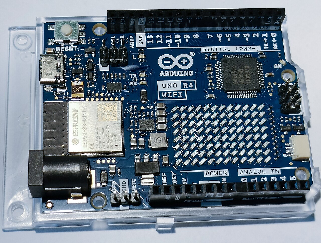
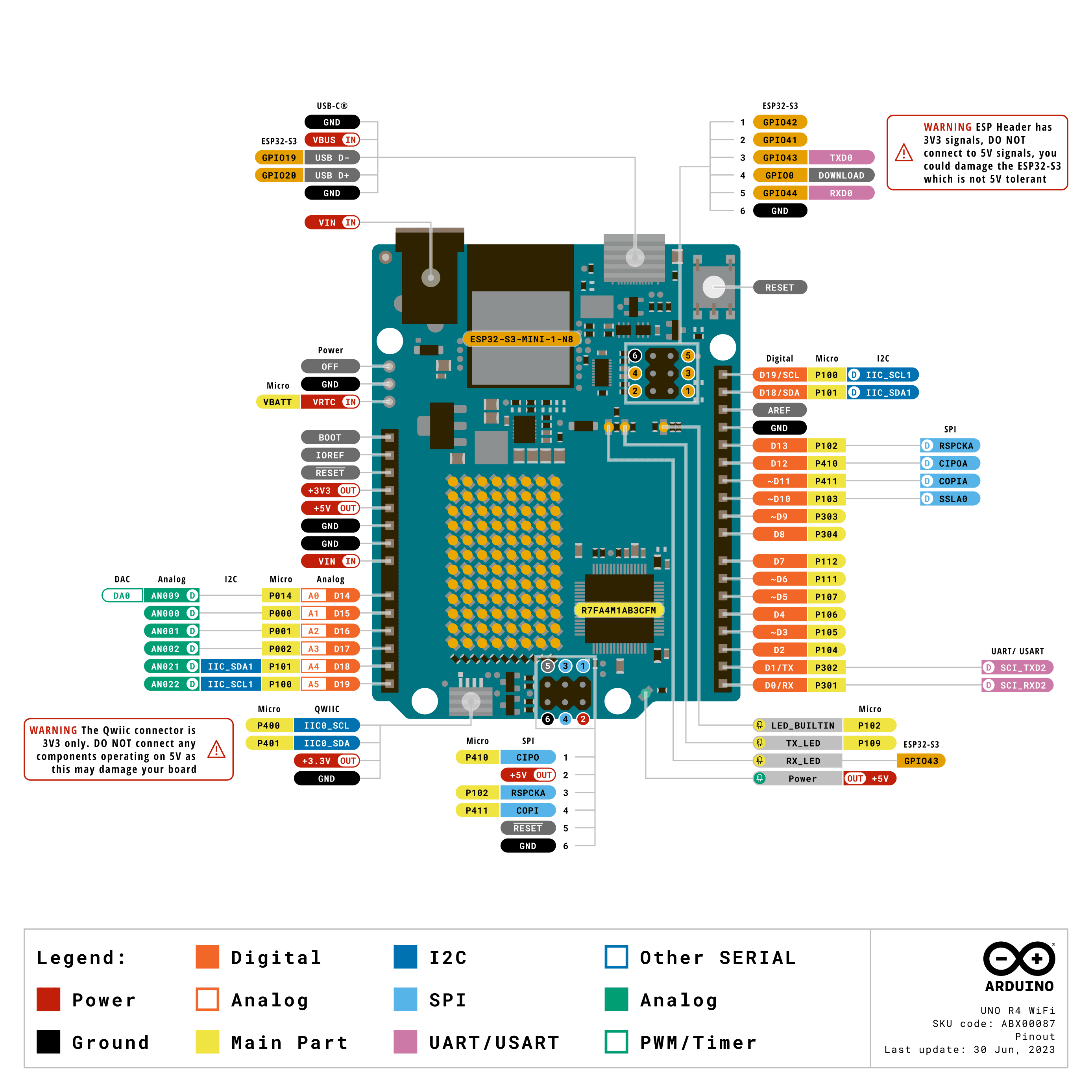
Pinout diagram
| Attr | Specs | verified |
|---|---|---|
main_mcu | Renesas RA4M1 (Arm Cortex-M4) @ 48 MHz, 32 KB SRAM, 256 KB flash; RTC, 12-bit DAC, CAN bus, USB HID (docs page). | ✔ |
co_processor | Espressif ESP32-S3 module for Wi-Fi (2.4 GHz) / Bluetooth®, "which can also be separately programmed via a specific header" (docs page). Module family: ESP32-S3-MINI (Espressif ESP32-S3 datasheet). | ✔ |
gpio | 14 digital I/O + 6 analog inputs at 5 V ("The RA4M1 and the GPIOs of this board operates on 5 V", docs page); ADC up to 14-bit, DAC 12-bit (docs — R4 family). | ✔ |
onboard_extras | 12×8 red LED matrix, Qwiic (JST) I²C connector, VRTC backup pin, OFF pin (store page), USB-C, SWD debug, op-amp (store page for the shared R4 feature set). | ✔ |
power | VIN or barrel jack 6–24 V (docs page). | ✔ |
current_limit | 8 ma | ✔ |
voltage_domains | ESP32-S3 section and the ESP header are 3.3 V only; the Qwiic connector is a 3.3 V secondary I²C bus (IIC0) (tech-specs note). | ✔ |
- Manufacturer: Arduino (arduino.cc / Arduino AG); main MCU by Renesas, radio module by Espressif.
- Year: Released June 2023 alongside the R4 Minima (Wikipedia — Arduino Uno).
- Status: Active, current product (store page, docs page).
- Price: €30.50 incl. VAT on the official store, retrieved 2026-10-13 (store page).
- Variants: base UNO R4 WiFi; sibling without radio is the UNO R4 Minima.
+ Strengths
- Two brains in UNO form factor: 48 MHz Cortex-M4 + ESP32-S3 radio co-processor, shield-compatible (store page).
- 12×8 LED matrix built in — graphics/animation without external parts (docs page).
- Qwiic connector for tool-free I²C sensor chains (store page).
- Separately programmable ESP32-S3 via its own header — rare dual-ecosystem setup (docs page).
- RTC, 12-bit DAC, HID, CAN, 24 V input, USB-C, SWD, op-amp inherited from the R4 line (docs page, store page).
- VRTC + OFF pin for RTC backup battery and controlled power-down of peripherals (store page).
− Weaknesses
- ESP header is 3.3 V only — "should not be connected to 5 V. This may damage your board" (tech-specs note).
- Qwiic is on a secondary I²C bus (IIC0) and 3.3 V only; you must init it with Wire1.begin instead of Wire (tech-specs note).
- 8 mA per-pin limit — the LED matrix and GPIO share this tighter budget vs AVR Unos; exceeding it "may damage your pin / board" (tech-specs note).
- Wi-Fi depends on the ESP32-S3 firmware being present/compatible — first-run and after ESP-side reflashing, the matching Wi-Fi firmware must be flashed before WiFi.begin works.
- Two-chip complexity: resets, uploads and serial routing involve both MCUs (e.g. ESP header, ESP32-S3 serial), a common confusion point for R3 users.
- AVR library incompatibility (different architecture core, ArduinoCore-renesas).
- Retour d'expérience expert expert — expert-arduino
- Petit retour après quelques semaines sur l'Uno R4 WiFi. Les points forts sont reels : la matrice 12x8 est super pratique pour le feedback visuel immediat et le connecteur Qwiic simplifie beaucoup le branchement des capteurs sans soudure. Par contre, attention aux pieges documentes. Le bus I2C du Qw… — expert-arduino
- Merci pour cet avertissement sur le voltage du header ESP ! J'ai failli faire la boulette en essayant de lire un capteur qui etait alimente en 5V via ce connecteur. Heureusement j'avais lu la doc juste a temps. Par contre, j'ai un souci avec le Wi-Fi. J'ai flashé un exemple basique mais la connexio… — maker_debutant
- Pour le Wi-Fi, c'est vrai que la gestion des deux puces ajoute une couche de complexite. Parfois il faut réinitialiser ou vérifier que le firmware est bien à jour via le Serial Monitor. L'autre point delicat que tu as mentionne est la limite de 8 mA par GPIO. Avec la matrice LED allumée, si tu bran… — bricoleur_78
Community feedback and projects
- UNO R4 WiFi USB CDC serial communication randomly stops after several hours on Windows 11 forum.arduino.cc
- UNO R4 WiFi RTC runs fast by about 1 second per minute forum.arduino.cc
- Uno R4 WiFi - CA Certificates using CertificateUploader forum.arduino.cc
- Continuous ADC with the UNO R4 forum.arduino.cc
- Arduino Uno R4 WiFi Factory Demo? forum.arduino.cc
Content not available yet.
- ESP header is 3.3 V only — "should not be connected to 5 V. This may damage your board" (tech-specs note).
- Qwiic is on a secondary I²C bus (IIC0) and 3.3 V only; you must init it with Wire1.begin instead of Wire (tech-specs note).
- 8 mA per-pin limit — the LED matrix and GPIO share this tighter budget vs AVR Unos; exceeding it "may damage your pin / board" (tech-specs note).
- Wi-Fi depends on the ESP32-S3 firmware being present/compatible — first-run and after ESP-side reflashing, the matching Wi-Fi firmware must be flashed before WiFi.begin works.
- Two-chip complexity: resets, uploads and serial routing involve both MCUs (e.g. ESP header, ESP32-S3 serial), a common confusion point for R3 users.
- AVR library incompatibility (different architecture core, ArduinoCore-renesas).
- Premier Blink sur la UNO R4 WiFi : la première UNO 32 bits debutant Schéma : IMG-uno-r4-wifi-debutant-1-ur4wifi-blink-ra4m1.svg — Arduino UNO R4 WiFi vue de dessus, câble USB-C branché, LED « L » (pin 13) surlignée avec une flèche, puce RA4M1 annotée « Cortex-M4 48 MHz », matrice LED 12x8 visible en bas de carte.
- Apprivoiser la matrice LED 12x8 intégrée debutant Schéma : IMG-uno-r4-wifi-debutant-2-ur4wifi-matrice-led-12x8.svg — gros plan sur la matrice LED 12x8 de l'UNO R4 WiFi, grille annotée colonnes 0 à 11 et lignes 0 à 7, flèches vers les broches 12 à 23 (colonnes) et GPIO internes 24 à 31 (lignes).
- Toucher capacitif : touchRead sans composant debutant Schéma : IMG-uno-r4-wifi-debutant-3-ur4wifi-touch-capacitif.svg — UNO R4 WiFi avec un fil nu relié à une broche tactile, doigt pointant sur le fil, moniteur série affichant deux niveaux (repos ~0, touché > 100), matrice LED affichant un smiley.
- Se connecter au WiFi et lire l'heure NTP (WiFiS3) intermediaire Schéma : IMG-uno-r4-wifi-intermediaire-1-ur4wifi-wifi-station-ntp.svg — UNO R4 WiFi avec antention WiFi en en-tête, puce ESP32-S3 annotée « modem WiFi 2,4 GHz + BLE », routeur à gauche, serveur NTP à droite, moniteur série affichant un horodatage.
- Inclinomètre sur la matrice : l'IMU LSM6DSV16X en I²C intermediaire Schéma : IMG-uno-r4-wifi-intermediaire-2-ur4wifi-imu-matrice.svg — UNO R4 WiFi inclinée sur la tranche, puce IMU LSM6DSV16X surlignée près du connecteur Qwiic, bus I²C A4/A5 annoté SDA/SCL, matrice LED affichant une flèche qui suit l'inclinaison.
- Serveur web embarqué : piloter la matrice depuis le navigateur intermediaire Schéma : IMG-uno-r4-wifi-intermediaire-3-ur4wifi-webserver-matrice.svg — UNO R4 WiFi reliée en WiFi à une box, un navigateur affichant un bouton ON/OFF, flèche HTTP GET /led=on vers la carte, matrice LED allumée ou éteinte.
- Horloge persistante : RTC à pile + resynchronisation NTP avance Schéma : IMG-uno-r4-wifi-avance-1-ur4wifi-horloge-rtc-ntp.svg — UNO R4 WiFi avec emplacement pile bouton du RTC surligné, symbole pile 3 V, serveur NTP à gauche, matrice LED affichant 12:34, horloge interne du RA4M1 annotée.
- Débogage pas à pas : CMSIS-DAP et Arduino Debug Launcher avance Schéma : IMG-uno-r4-wifi-avance-2-ur4wifi-debug-cmsis-dap.svg — UNO R4 WiFi avec deux ports USB-C annotés (HIC/débogueur à gauche, USB natif du RA4M1 à droite), écran d'IDE avec point d'arrêt rouge sur une ligne, pile d'appels et variables affichées.
- Bus CAN FD : relier deux R4 avec un transceiver externe avance Schéma : IMG-uno-r4-wifi-avance-3-ur4wifi-can-fd.svg — deux UNO R4 WiFi face à face, chacune reliée à un module transceiver CAN FD, paires de fils CANH/CANL reliant les deux modules, résistance 120 Ω aux deux extrémités, matrice LED affichant un compteur reçu.
Code library — examples written for this board
clignotante.inoArduinobouton-poussoir.inoArduinodac-analogique.inoArduinoentree-analogique.inoArduinopwm-respiration.inoArduinoservo-balayage.inoArduinocapteur-dht11.inoArduinoruban-neopixel.inoArduinomatrice-led.inoArduinowifi-scan.inoArduino
Examples and repos found online
- arduino/ArduinoCore-renesas github.com
- arduino/uno-r4-wifi-usb-bridge github.com
- arduino-libraries/Servo github.com
- misan/UNOR4text github.com